KIA Niro: Blower Unit
Blower Unit Components and components location
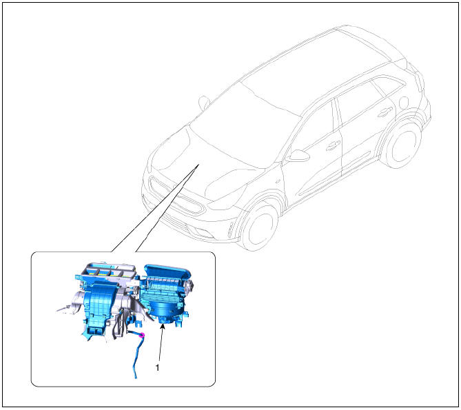
- Blower unit assembly
Components
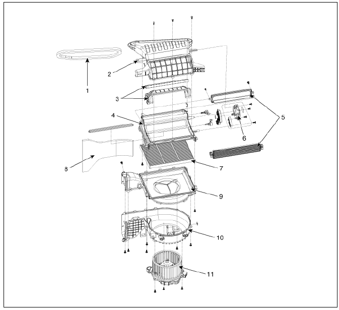
- Blower Intake Seal
- Intake Duct Case (Upper)
- Intake Door Assembly
- Intake Duct Case (Lower)
- Air Filter Cover
- Intake Actuator
- Air Filter
- Anti Noise Pad
- Blower Case (Upper)
- Blower Case (Lower)
- Blower Motor assembly
Blower Unit Repair procedures
Replacement
Warning
When prying with a flat-tip screwdriver or a prying trim tool, wrap a protective tape around the related parts and the tool to prevent damage.
- Disconnect the negative (-) battery terminal.
- Recover the refrigerant with a recovery / recycling / charging station.
Warning
If PAG oil mixes into the POE oil of the system, dielectric breakdown may occur due to decreased volumetric resistivity and the A/C compressor may not work.
- When the engine is cool, drain the engine coolant from the radiator.
(Refer to Engine Mechanical System - "Coolant")
- Remove the cowl top cover.
(Refer to Body - "Cowl Top Cover")
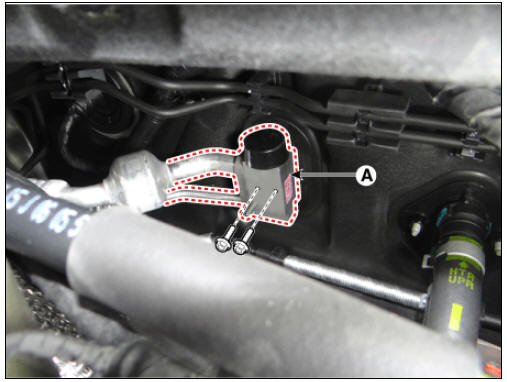
- Remove the expansion valve cover (A) after loosening the bolt.
Tightening torque : 7.8 - 11.8 N*m ( 0.8 - 1.2 kgf*m, 5.8 - 8.7 Ib*ft)
Warning
- Plug or cap the lines immediately after disconnecting them to avoid moisture and dust contamination.
- When installing, always replace the o-ring with a new one.
- Remove the inlet (A) and outlet (B) heater hoses from the heater core.
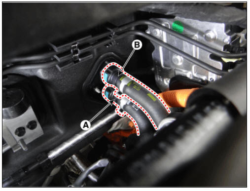
Warning
Engine coolant will run out when the hoses are disconnected; drain it into a clean drip pan. Be sure not to let coolant spill on electrical parts or painted surfaces. If any coolant spills, rinse it off immediately.
- Loosen the cowl cross bar assembly mounting bolts (A).
- Remove the front seat assemblies on both sides.
(Refer to Body - "Front Seat Assembly")
- Remove the floor console.
(Refer to Body - "Floor Console Assembly")
- Remove the front pillar trims on both sides.
(Refer to Body - "Front Pillar Trim")
- Remove the cowl side trims on both sides.
(Refer to Body - "Cowl Side Trim")
- Remove the crash pad lower panel.
(Refer to Body - "Crash Pad Lower Panel")
- Remove the steering column shroud lower panel.
(Refer to Body - "Steering Column Shroud Panel")
- Remove the steering wheel.
(Refer to Steering System - "Steering Wheel")
- Remove the multifunction switch.
(Refer to Body Electrical System - "Multifunction Switch")
- Lower the steering column after loosening the mounting bolts.
(Refer to Steering System - "Steering Column and Shaft")
- Remove the front door scuff trim.
(Refer to Body - "Door Scuff Trim")
- Remove the shift lever assembly.
(Refer to DCT(Double Clutch Transmission) System - "Shift Lever")
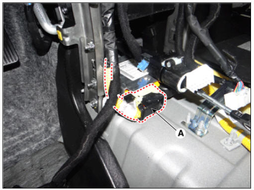
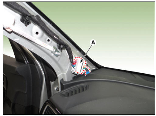
- Disconnect the airbag control module (SRSCM) connector (A).
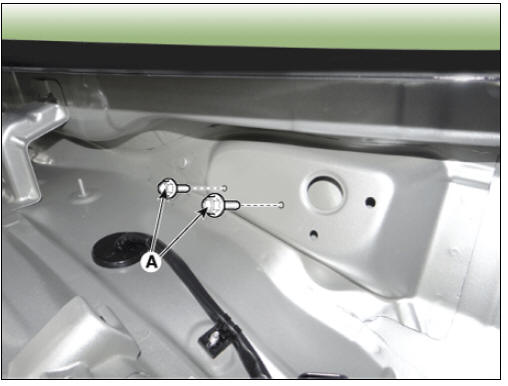
- Remove the rear duct (A).
LH
RH
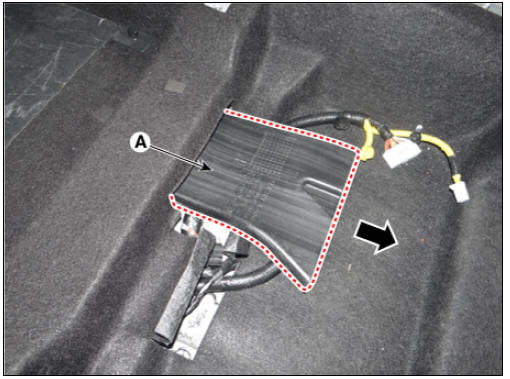
- Put away the floor carpet (A).
Driver side
Passenger side
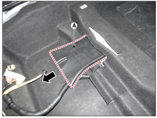
- Remove the mounting bolt and remove the rear heating ducts (A).
Driver side
Passenger side
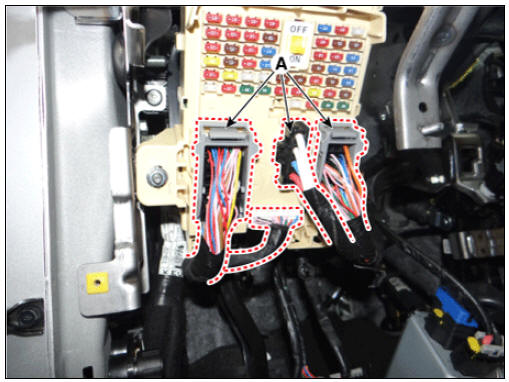
- Disconnect the passenger compartment junction box connectors (A).
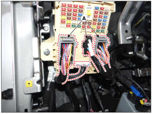
- Disconnect the multi box connectors (A).
LH
RH
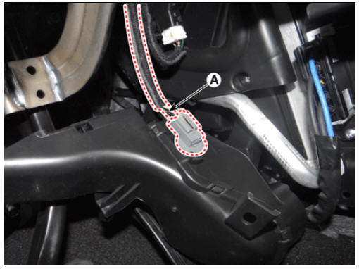
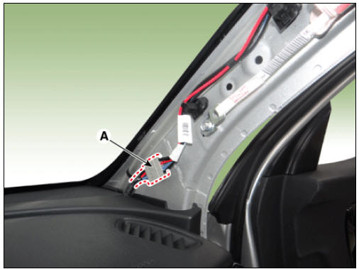
- Disconnect the connector (A) and the mounting clips in the front pillar.
LH
RH
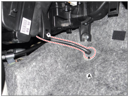
- Remove the drain hose (A).
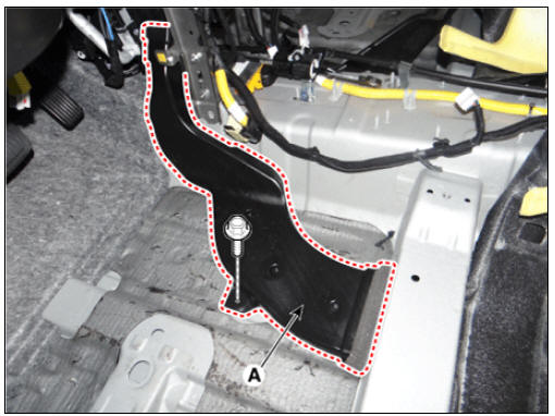
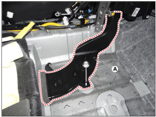
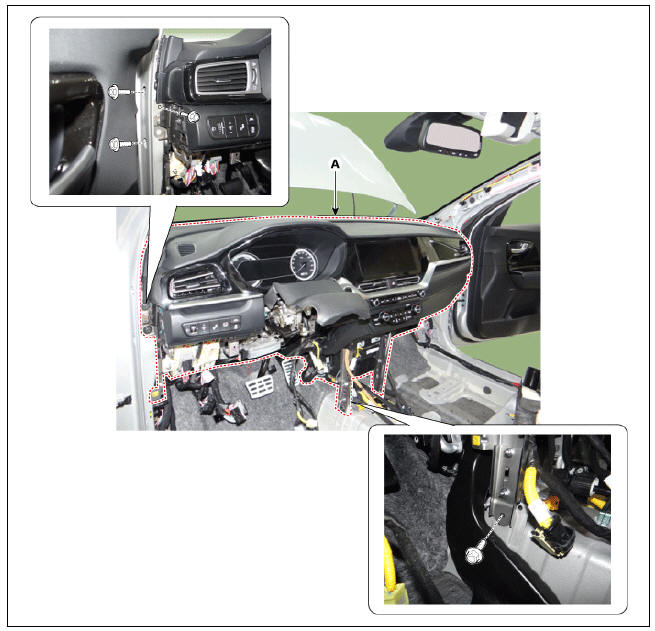
- After loosening the bolts, remove the main crash pad and cowl cross bar assembly (A) altogether.
- Disconnect the heater & blower unit connectors.
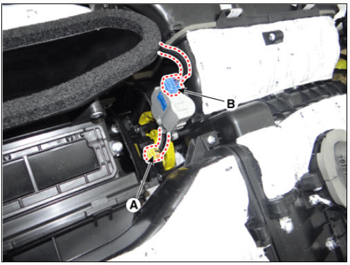
(1) Disconnect the intake actuator connector (A).
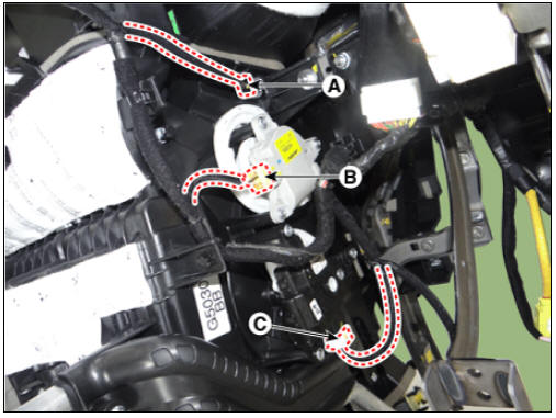
(2) Disconnect the mode control actuator (A) and auto defogging actuator (B) connectors, and then remove the wiring fixing clip.
(3) Disconnect the duct sensor (A), mode control actuator (B) and temperature control actuator (C) connectors, and then remove the wiring mounting clips.
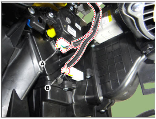
(4) Temperature actuator (A), to remove the evaporator temperature sensor (B) connector, to remove the wiring fixing clip.
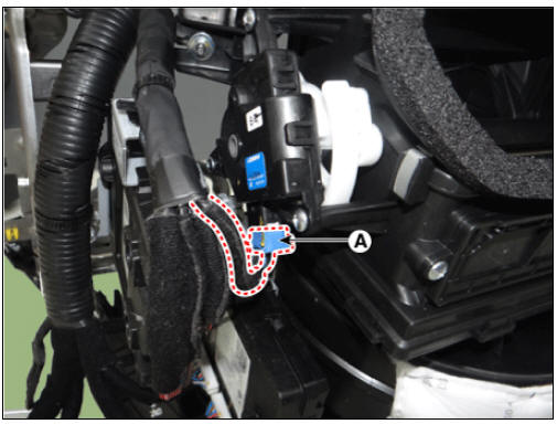
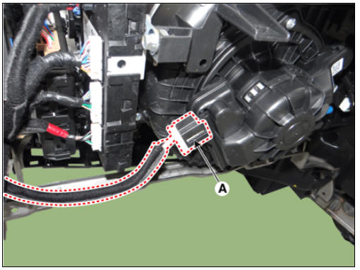
(5) Remove the blower motor connector (A).
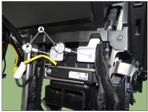
- Loosen the heater & blower unit mounting bolt (A).
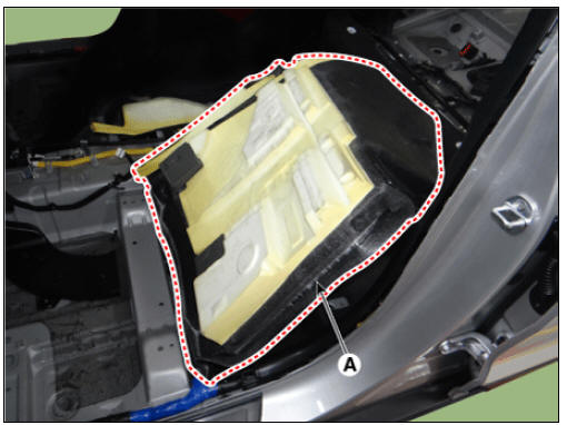
- Loosen the mounting nuts and remove the heater and blower units (A) from the crash pad.
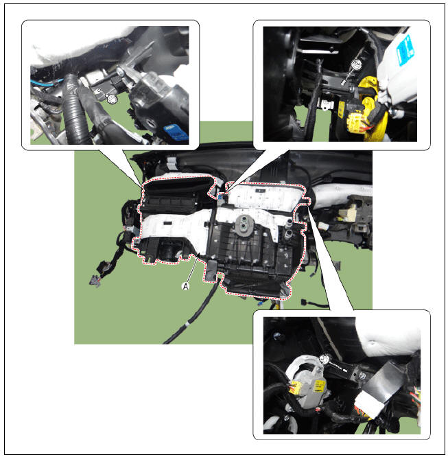
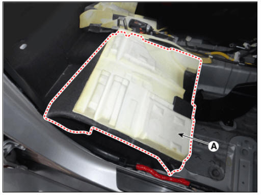
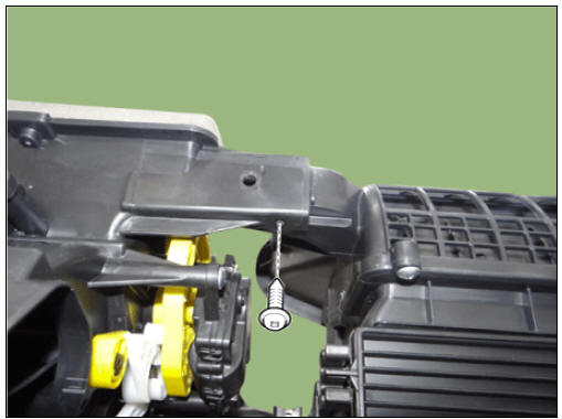
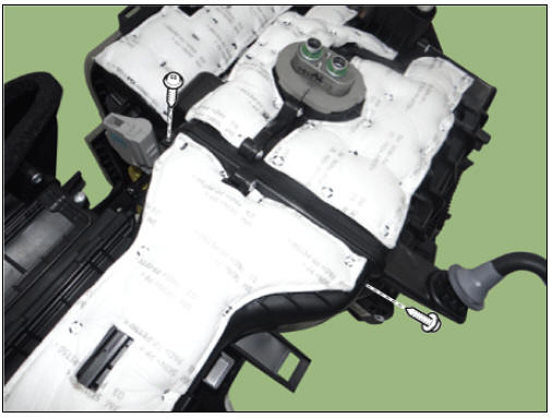
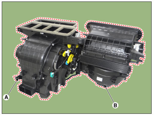
- Separate the blower unit (B) from the heater unit (A) after loosening the screws.
- Install in the reverse order of removal
READ NEXT:
 Blower Motor Repair procedures | Climate Control Air Filter Repair procedures
Inspection
Operate the heater controls at IGN2 to ensure that the motor is running.
Battery (+)
Input signal
Ë—
Ground
If the blower motor does not operate well, substitute with a known-good blower m
Intake Actuator
Intake Actuator Components and components location
Intake actuator
Description
Located in the blower unit, the intake actuator regulates the intake door
based on the signal from the
control unit. Pressing the intake selection switch wi
SEE MORE:
Sub Frame Repair procedures
Removal
Disconnect the battery negative cable.
Remove the universal bolt (A).
Tightening torque :
32.4 - 37.3 N*m (3.3 - 3.8 kgf*m, 23.9 - 27.5 lb*ft)
Warning
Keep neutral range to prevent damaging the clock spring inner
cable w
Rear View Monitor settings
Rear View Monitor (RVM) (if
equipped)
Rear View Monitor shows the area
behind the vehicle to assist you when
parking or backing up.
Detecting sensor
Kia NIRO Hybrid
Rear view camera
Kia Niro EV
Wide-rear view camera
Refer to the pic
Categories
- Home
- KIA Niro EV, Hybrid - Second generation - (SG2) (2021-2024) - Owner's manual
- Kia Niro - First generation - (DE) (2017-2022) - Service and Repair Manual
- Contact Us