KIA Niro: Stop Lamp Switch Repair procedures
Removal
- Turn ignition switch OFF and disconnect the negative (-) battery terminal.
- Remove the crash pad lower panel.
(Refer to Body - "Crash Pad")
- Remove the knee air bag.
(Refer to Restraint - "Knee Airbag(KAB) Module")
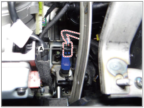
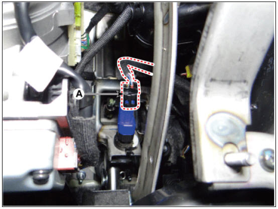
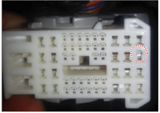
- Disconnect the stop lam switch connector (A).
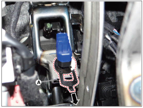
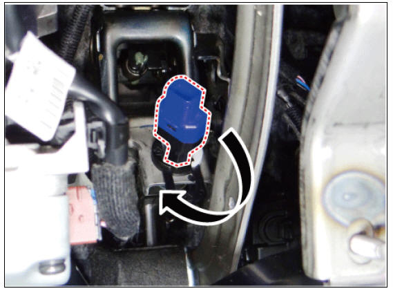
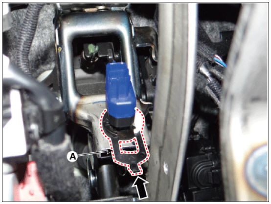
- Pull the locking plate (A) as indicated by the arrow.
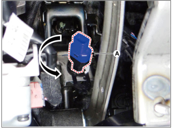
- Turn brake switch 45º counterclockwise and remove it.
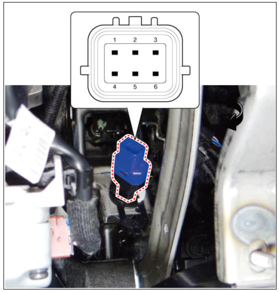
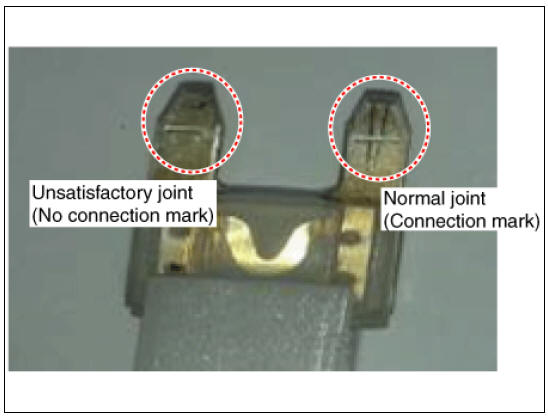
- Inspect a removed stop lamp switch along the below procedures.
(1) Confirm a normal connection with terminal part
- A confirmation can be made to see if the connector has been secured properly and if a connection mark is present.
Installation
- Insert fully the stop lamp switch as hiding contact part and than turn the stop lamp switch 45º clockwise.
- Assemble locking plate (A) by pushing.
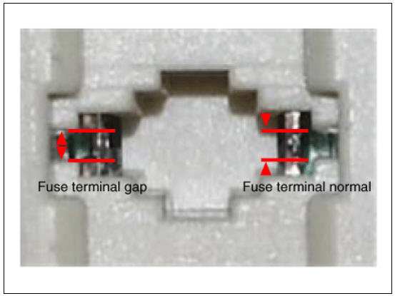
- Confirm the gap (A) between stop lamp switch and bracket.
Stop lamp clearance : 1.0 - 2.0 mm (0.04 - 0.08 in.)
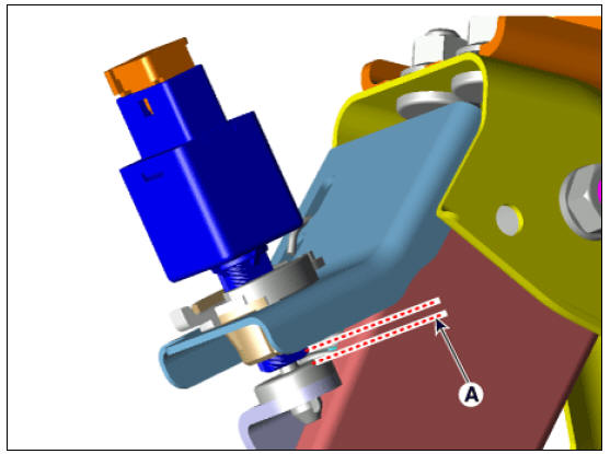
Warning
If the gap between stop lamp switch and bracket is not 1.0 - 2.0 mm(0.04 - 0.08in), perform the above process again.
- Connect the stop lamp switch connector (A).
- Install the knee air bag.
(Refer to Restraint - "Knee Airbag (KAB) Module")
- Install the lower crash pad.
(Refer to Body - "Crash Pad")
Inspection
- Fuse inspection
Mount the test fuse to the switch fuse and relay fuse part to confirm a normal joint fit.
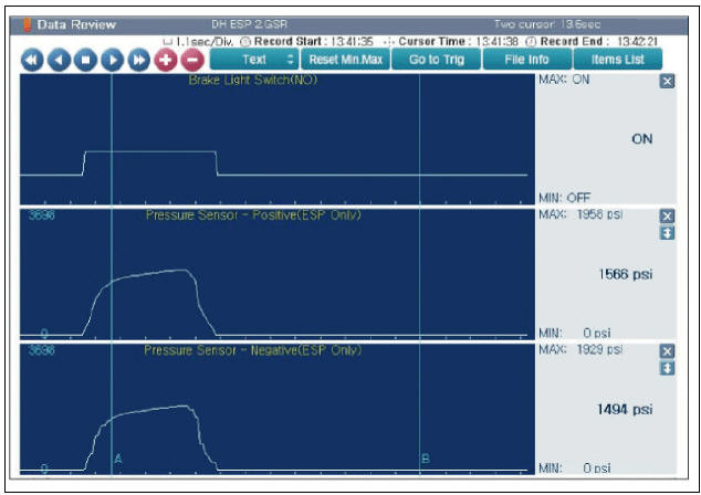
- GDS Data Analysis
- Analyze GDS data and confirm if there is anything wrong with the stop
lamp switch.
(1) Connect the GDS to the self-diagnosis connector.
(2) Turn the spark switch on (3) Step on the brake pedal.
(4) Inspect the "brake switch" category that displays the "sensor data" GDS.)
Normal waveform : The pressure sensor signal value will change according to the brake ON/OFF switch.
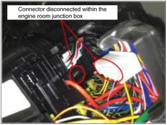
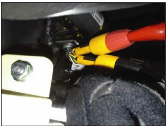
- Inspection of connector by each part
Check to see whether or not each connector has been damaged, or terminal surge, or incomplete connection has taken place
Engine room junction box
ABS/VDC control module
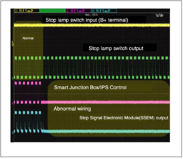
- Inspect the stop lamp circuit
Connect probe to each terminal wire and confirm oscilloscope waveform.
Stop lamp switch input/output
Oscilloscope waveform screen
READ NEXT:
 Parking Brake Assembly Repair procedures
Parking Brake Assembly Components and components location
Parking brake pedal
Parking brake cable
Equalizer assembly
Parking Brake Assembly Repair procedures
Removal
Turn ignition switch OFF and disconnect the negative (-) battery
Parking Brake Cable Repair procedures
Removal
Turn ignition switch OFF and disconnect the negative (-) battery
terminal.
Remove the crash pad lower panel.
(Refer to Body - "Crash Pad")
Remove the knee air bag.
(Refer to Restraint - "Knee Airbag(KAB) Module&q
SEE MORE:
Driver Attention Warning malfunction and limitations
Driver Attention Warning malfunction
A: Check Driver Attention Warning
(DAW) system
When Driver Attention Warning is not
working properly, the warning message
will appear on the cluster for several seconds, and the
master ( ) warning light
Electronic Stability Control (ESC)
Electronic Stability Control (ESC)
Electronic Stability Control (ESC) is
designed to stabilize the vehicle during
cornering maneuvers.
ESC is not a substitute for safe driving
practices. Factors including speed, road
conditions and driver ste
Categories
- Home
- KIA Niro EV, Hybrid - Second generation - (SG2) (2021-2024) - Owner's manual
- Kia Niro - First generation - (DE) (2017-2022) - Service and Repair Manual
- Contact Us