KIA Niro: Cylinder Head Cover Components and components location | Cylinder Head Cover Repair procedures
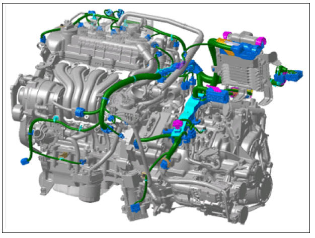
Components
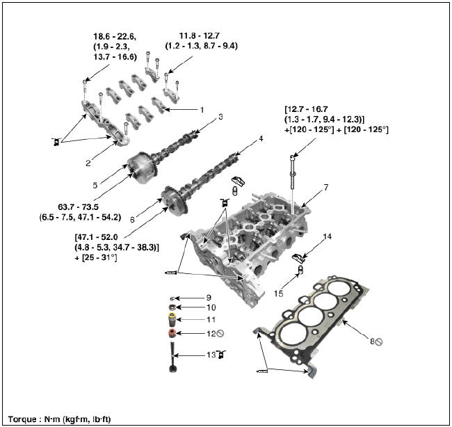
- Camshaft bearing cap
- Camshaft front bearing cap
- Exhaust camshaft
- Intake camshaft
- Exhaust CVVT assembly
- Intake CVVT assembly
- Cylinder head
- Cylinder head gasket
- Retainer lock
- Retainer
- Valve spring
- Valve stem seal
- Valve
- Swing arm
- Hydraulic lash adjuster (HLA)
Cylinder Head Cover Components and components location
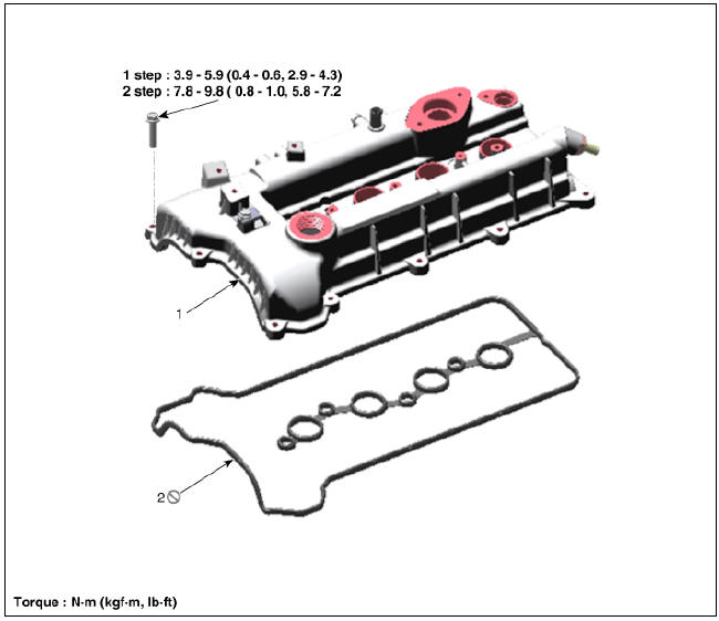
- Cylinder head cover
- High pressure fuel pump gasket
- Cylinder head cover gasket
Cylinder Head Cover Repair procedures
Removal
Engine removal is not required for this procedure.
Warning
- Use fender covers to avoid damaging painted surfaces.
- To avoid damage, unplug the wiring connectors carefully while holding the connector portion.
Warning
Mark all wiring and hoses to avoid misconnection.
- Disconnect the negative battery terminal.
- Remove the air cleaner assembly.
(Refer to Intake And Exhaust System - "Air Cleaner")
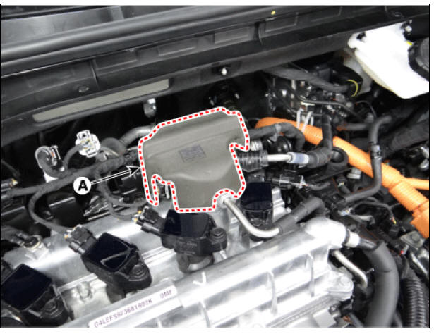
- Remove the high pressure fuel pump foam (A).
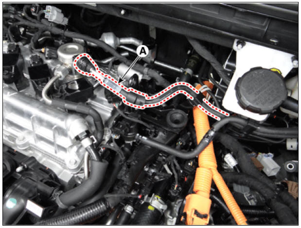
- Disconnect the fuel hose (A).
- Disconnect the wiring connectors and harness clamps and remove the connector brackets around the cylinder head cover.
- Disconnect the reservoir tank coolant hose (A) and then drain the coolant from the reservoir tank.
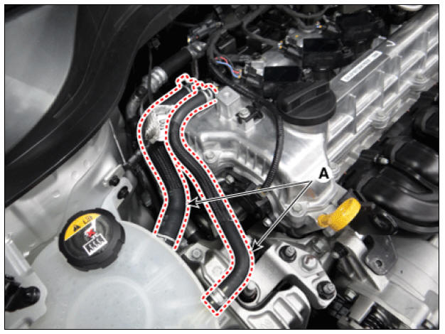
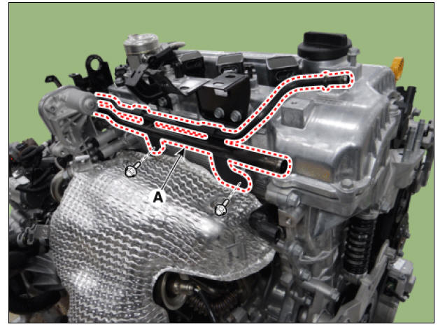
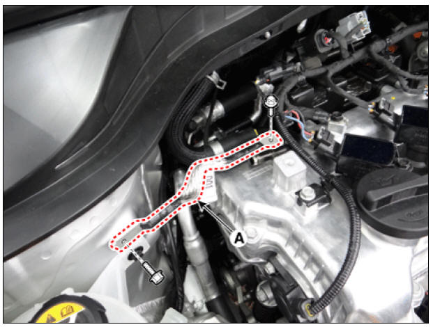
- Separate the water return & degas pipe (A).
Tightening torque : 18.6 - 23.5 N*m (1.9 - 2.4 kgf*m, 13.7 - 17.4 lb*ft)
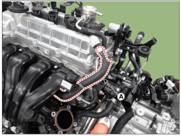
- Disconnect the positive crankcase ventilation (PCV) hose (A).
- Remove the high pressure fuel pump.
(Refer to Engine Control/Fuel System - "High Pressure Fuel Pump")
- Remove the ignition coils.
(Refer to Engine Electrical System - "Ignition Coil")
- Disconnect the engine ground cable (A).
Tightening torque : 10.8 - 13.7 N*m (1.1 - 1.4 kgf*m, 8.0 - 10.1 lb*ft)
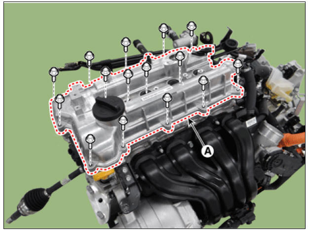
- Remove the cylinder head cover (A).
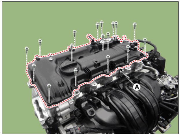
Warning
Unfasten the bolts in the sequence shown. 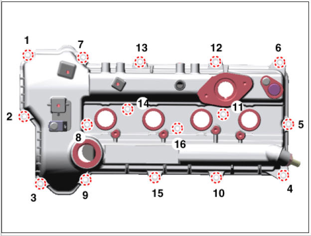
Installation
- Install the cylinder head cover.
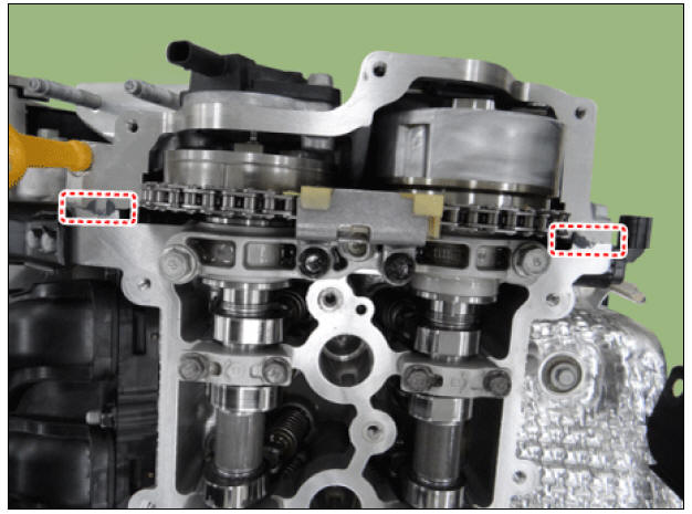
(1) The hardening sealant should be removed from the cylinder head cover and the gap between the timing chain cover and the cam carrier before assembling the cylinder head cover.
(2) Apply engine oil on the lip portion of the oil seal on the cover and outer surface of the spark plug pipes.
(3) Assemble within 5 minutes of applying sealant on the gap between the timing chain cover and the cam carrier.
Bead width : 2.0 - 3.0 mm (0.08 - 0.12 in.)
Sealant : Threebond 1217H or equivalent
(4) Install the new cylinder head cover gasket (A).
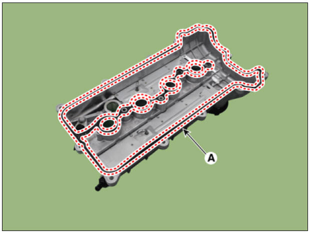
(5) Install the cylinder head cover (A) by tightening the bolts, in several passes, in the sequence shown.
Tightening torque :
1st step: 3.9 - 5.9 N*m (0.4 - 0.6 kgf*m, 2.9 - 4.3 lb*ft)
2nd step: 7.8 - 9.8 N*m (0.8 - 1.0 kgf*m, 5.8 - 7.2 lb*ft)

Warning
- Do not reuse cylinder head cover gasket.
- Before installing the cylinder head cover, make sure the cylinder head cover gasket is not separated from the cylinder head cover gasket groove.
- It is not recommended to start engine or perform pressure test within 30 minutes of assembling the cylinder head cover.
- Install the remaining parts in the reverse order of removal.
READ NEXT:
 CVVT & Camshaft Description and operation
Description
Continuous Variable Valve Timing (CVVT) system advances or retards the valve
timing of the intake and exhaust valve in accordance with the ECM control signal
which is calculated by the engine speed and load.
By controlling CVVT, th
SEE MORE:
Remote Smart Parking Assist settings
Remote Smart Parking Assist uses vehicle
sensors to help the driver park and
exit parking spaces remotely from outside
the vehicle by controlling the steering
wheel, vehicle speed and gearshifts.
Remote Operation function may be
operate
Highway Driving Assist operation
Displaying operating status
You can see the status of the Highway
Driving Assist operation in the Driving
Assist view on the cluster. Refer to "LCD
display modes"
Operating State
Standby State
Highway Driving Assist will be d
Categories
- Home
- KIA Niro EV, Hybrid - Second generation - (SG2) (2021-2024) - Owner's manual
- Kia Niro - First generation - (DE) (2017-2022) - Service and Repair Manual
- Contact Us