KIA Niro: Alignment Repair procedures
Front wheel alignment
Warning
When using a commercially available computerized wheel alignment equipment to inspect the front wheel alignment, always position the vehicle on a level surface with the front wheels facing straight ahead.
Prior to inspection, make sure that the front suspension and steering system are in normal operating condition and that the tires are inflated to the specified pressure.
Toe
B - A > 0: Toe in (+)
B - A < 0: Toe out (-)
Toe adjustment
- Loosen the tie rod end lock nut.
- Remove the bellows clip to prevent the bellows from being twisted.
- Adjust the toe by screwing or unscrewing the tie rod. Toe adjustment should be made by turning the right and left tie rods by the same amount.
Toe-in
Total : 0.1º +- 0.2º
Individual : 0.05º +- 0.1º
- When completing the toe adjustment, install the bellows clip and tighten the tie rod end lock nut to specified torque.
Tightening torque: 49.0 - 53.9 N*m (5.0 - 5.5 kgf*m, 36.2 - 39.8 lb*ft)
- Perform the Steering Angle Sensor calibration.
- MDPS : (Refer to Steering System - "Electric Power Steering")
Camber and Caster
Camber and Caster are pre-set at the factory, so they do not need to be adjusted. If the camber and caster are not within the standard value, replace or repair the damaged parts and then inspect again.
Camber angle : -0.4º+-0.5º
Caster angle : 4.4º+-0.5º
Rear wheel alignment
Warning
When using a commercially available computerized wheel alignment equipment to inspect the rear wheel alignment, always position the vehicle on a level surface.
Prior to inspection, make sure that the rear suspension system is in normal operating condition and that the tires are inflated to the specified pressure.
Toe
B - A > 0: Toe in (+)
B - A < 0: Toe out (-)
Toe adjustment
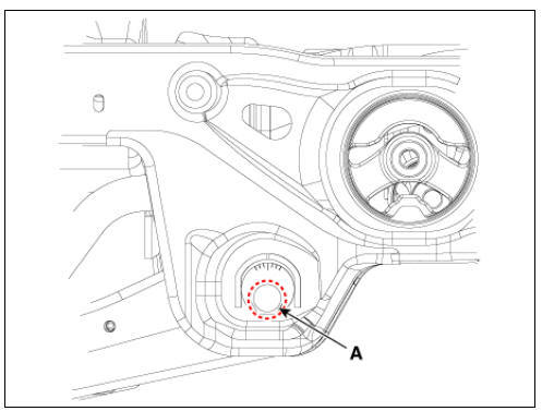
- Loosen the nut holding the assist arm cam bolt (A).
- Adjust rear toe by turning the rear assist arm cam bolt (A) clockwise or counter clockwise. Toe adjustment should be made by turning the right and left cam bolt by the same amount.
Toe-in
Total : 0.14º+-0.2º
Individual : 0.07º+-0.1º
- When completing the toe adjustment, tighten the nut to specified torque.
Tightening torque: 107.9 - 117.7 N*m (11.0 - 12.0 kgf*m, 79.6 - 86.8 lb*ft)
Camber
- Loosen the nut holding the lower arm cam bolt (A).
- Adjust rear camber by turning the rear lower arm cam bolt (A) clockwise or counterclockwise. Camber adjustment should be made by turning the right and left cam bolt by the same amount.
Camber : -1.2º+-0.5º
One scale turn : About 0.2º
Cam bolt (LH) : Clockwise camber (-)
Cam bolt (RH) : Clockwise camber (+)
- When completing the rear camber adjustment, tighten the nut to specified torque.
Tightening torque : 107.9 - 117.7 N*m (11.0 - 12.0 kgf*m, 79.6 - 86.8 lb*ft)
READ NEXT:
 Tire Pressure Monitoring System
Tire Pressure Monitoring System / Components And Components Location
BCM (TPMS)
TPMS Sensor (FL)
TPMS Sensor (RL)
TPMS Sensor (RR)
TPMS Sensor (FR)
Description
TREAD Lamp
Tire Under Inflation / Leak Warning.
Turn on c
Troubleshooting - Tire Pressure Monitoring System
TPMS Inspection method
Inspection
Warning
Find the inspection number by referring to the table above.
The following content is irrelevant of the inspection procedure.
Warning lamp types
Stays on without blinking : Low pressure tir
TPMS Sensor Repair procedures
Removal
Remove the valve core and deflate the tire.
Remove the side of the tire bead area from the wheel using tire changing
machine .
Warning
The tire bead should be broken approx. 90º from the valve side
of the wheel. The
SEE MORE:
Rear Seat Assembly | Rear Seat Back Cover
Rear seat back assembly
Rear seat cushion covering
Rear seat cushion pad
Rear seat cushion heater
Rear seat armrest
Rear seat back covering
Rear seat back pad
Rear seat back frame
Rear seat headrest guide
Power Door Lock Module Repair procedures
Inspection
Warning
When removing with a flat-tip screwdriver or remover, wrap
protective tape around the tools to
prevent damage to components.
When removing the interior trim pieces, use a plastic panel
removal tool not to damage the
Categories
- Home
- KIA Niro EV, Hybrid - Second generation - (SG2) (2021-2024) - Owner's manual
- Kia Niro - First generation - (DE) (2017-2022) - Service and Repair Manual
- Contact Us