KIA Niro: Hybrid Motor Control System
Kia Niro - First generation - (DE) (2017-2022) - Service and Repair Manual / Hybrid Motor System / Hybrid Motor Control System
Description
- The Hybrid Power Control Unit (HPCU), composed of various components, is the core device among the Power Electronics devices that acts as the brain.
- It comprises of the Hybrid Control Unit (HCU), an inverter Motor Control Unit (MCU), the Generator Control Unit (GCU)) and the Low-voltage DC-DC Converter (LDC).
Component
location
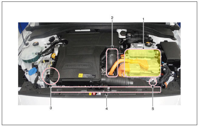
- HPCU (Hybrid Power Control Unit) (LDC+MCU+HCU+Reservoir)
- Hybrid drive motor
- Hybrid starter generator (HSG)
- Electrical radiator
- Electric water pump (EWP)
Components
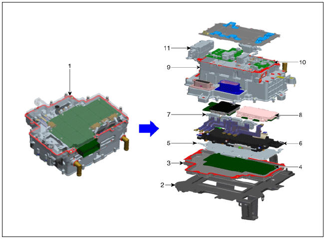
- HPCU (Hybrid Power Control Unit)
- HPCU tray
- HPCU cover
- Integrated board (MCU / HCU / LDC)
- Shield plate
- Capacitor
- Current sensor module
- Gate board + Power module
- Heat sink (water - cooled)
- LDC (Low voltage DC - DC Converter)
- High - voltage junction box
Inverter (MCU)
- An inverter supplies AC current to the drive motor and HSG.
- Depending on the driving conditions, the drive motor and HSG of the integrated board (control board) may act as a generator.
Integrated board (control board)
- One CPU controls two motors (drive motor and HSG)
- Sensors send the position, current, and temperature information to the CPU. The CPU generates the pulse width modulation signal and sends it to the gate board.
Capacitor
- Capacitor is an energy storage device for smoothing the current.
Current sensor
- Current sensor measures the current that flows through the motor, and is attached to each phase of a 3 - phase busbar.
Power module
- Power module has six switches that are used to convert DC current to AC current.
Heat sink
- Heat sink dissipates the heat of the coolant and is located between the power module and the cooling path.
Repalcement
- Replace the HPCU.
(Refer to Hybrid Control System- "Hybrid Power Control Unit")
Removal
Warning
- Be sure to read and follow the "General Safety Information and Caution" before doing any work related with the high voltage system. Failure to follow the safety instructions may result in serious electrical injuries.
- Be sure to shut off the high voltage before doing any work related with the high voltage system (Refer to "High Voltage Shut-off Procedure") . Failure to follow the safety instructions may result in serious electrical injuries.
- Remove the hybrid power control unit (HPCU).
(Refer to Hybrid Control System - "Hybrid Power Control Unit (HPCU)")
Warning
MCU is integrated into the HPCU and cannot be disassembled. Refer to "HPCU" for the removal or installation of MCU.
Installation
Warning
- Be sure to read and follow the "General Safety Information and Caution" before doing any work related with the high voltage system. Failure to follow the safety instructions may result in serious electrical injuries.
- Be sure to shut off the high voltage before doing any work related with the high voltage system (Refer to "High Voltage Shut-off Procedure") . Failure to follow the safety instructions may result in serious electrical injuries.
- Install the hybrid power control unit (HPCU).
(Refer to Hybrid Control System - "Hybrid Power Control Unit (HPCU)")
Warning
MCU is integrated into the HPCU and cannot be disassembled. Refer to "HPCU" for the removal or installation of MCU.
READ NEXT:
 Resolver Sensor | Motor Temperature Sensor
Description
The accurate position of the rotor must be known at all times to ensure maximum output control of the motor.
Part Circuit Diagram
Hybrid Drive Motor
HSG
Resolver Sensor Repair procedures
Inspection
Hybrid Drive Motor
Hybrid Motor Cooling System
Description
The Hybrid Power Control Unit (HPCU) uses various semiconductors that are
supplied with high voltage, hence generating
more heat than engine combustion devices. Overheating can decrease the
efficiency of control devices, restrict pr
SEE MORE:
Electrical Circuit Inspection Procedure
Open Circuit Test
Procedures for Open Circuit
Continuity Check
Voltage Check
If an open circuit occurs (as seen in (FIG. 1)), it can be found by
performing Step 2 (Continuity Check Method) or Step 3
(Voltage Check Method) as shown b
Opening the fuel filler door (Plug-in hybrid vehicle)
Stop the engine. To open the fuel filler
door, push the fuel filler door opener
button.
Wait until the fuel tank is depressurized.
The message is displayed when
the fuel filler door unlocks after the
fuel tank is depressurized.
Categories
- Home
- KIA Niro EV, Hybrid - Second generation - (SG2) (2021-2024) - Owner's manual
- Kia Niro - First generation - (DE) (2017-2022) - Service and Repair Manual
- Contact Us