KIA Niro: Button Engine Start System / Description And Operation
Button Engine Start System / Components And Components Location
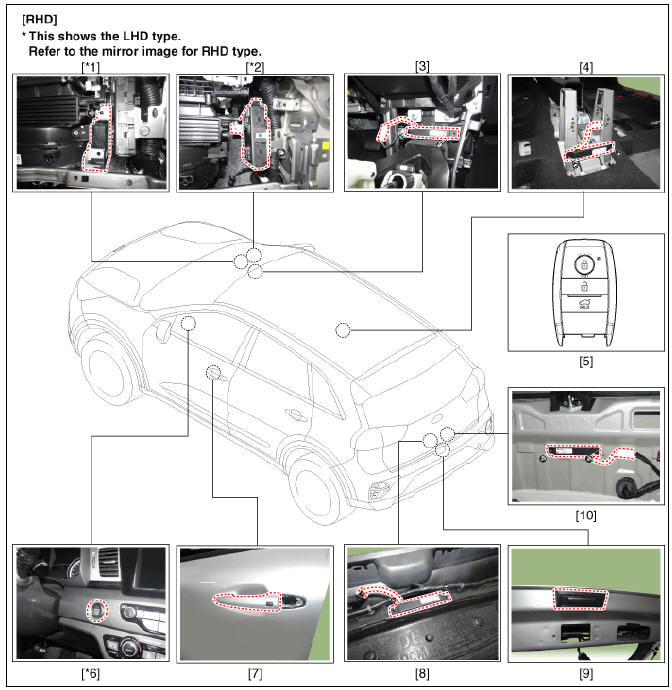
- Body control module (BCM)
- Smart key unit (SMK)
- Interior antenna 1
- Interior antenna 2
- FOB key
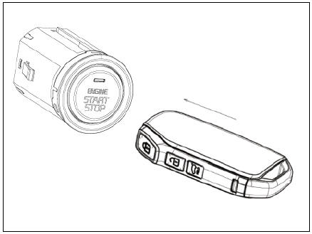
- Start Stop Button (SSB)
- Door handle & door antenna
- Bumper antenna
- Liftgate open switch
- Liftgate antenna
Button Engine Start System / Schematic Diagrams
Description
System Overview
The System offers the following features:
- Changing the state of engine ignition and power by using the start button.
- Controlling external relays for ACC / IGN1 / IGN2 terminal switching and STARTER, without use of mechanical ignition switch.
- Indicating the vehicle status on display by using explicit messages.
- Immobilizer function by LF transponder communication between fob and fob holder.
- Redundant architecture for high system dependability.
- Interface with Low Speed CAN vehicle communication network.
- Interface with LIN vehicle communication network depending on platform.
The RKE and SMART KEY functions are not considered part of this Button Engine Start system and are specified in a separate system.
System Main Function
- Switching of ACC / IGN1 / IGN2 terminals.
- Control of the STARTER relay BAT line (high side) based on communication with EMS ECU.
- Management of the Immobilizer function.
- Management of BES warning function.
Wireless Communications
The electric wave is used to exchange information between vehicle and FOB key. For now, button engine start is applied with smart key FOB key together.
Smart key function is explained separately so refer to the corresponding system contents.
System flowchart
System Block Diagram
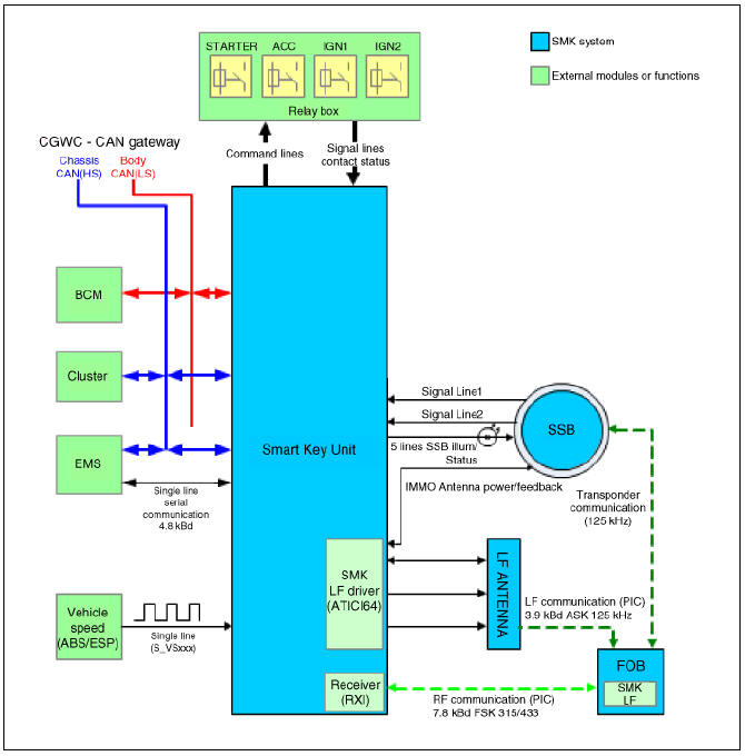
Smart Key Unit
The SMK manages all function related to:
- "Start Stop Button (SSB) monitoring"
- "Immobilizer communication" (with Engine Management System unit for immobilizer release)
- "Authentication server" (Validity of Transponder and in case of Smart Key option Passive Fob authentication )
- "System consistency monitoring"
- "System diagnosis"
- Control of display message / warning buzzer
- Control of SSB LEDs (illumination, clamp state)
The smart key unit masters the entire button engine start system.
It collects information about vehicle status from other modules (vehicle speed, alarm status, driver door open...), reads the inputs (e.g. SSB, Capacitive Sensor / Lock Button, PARK position Switch), controls the outputs (e.g. exterior and interior antennas), and communicates with others devices via the CAN network as well as a single-line interfaces.
The SMK manages the functions related to the "terminal control" by activating external relays for ACC, IGN1 and IGN2. This unit is also responsible for the control of the STARTER relay.
The SMK is also controlling the illumination of the SSB as well as the "system status indicator", which consists of 2 LEDs of different color. The illumination of the fob holder is also managed by the SMK.
The SMK reads the inputs (Engine fob in, vehicle speed, relays contact status), controls the outputs (Engine relay output drive), and communicates with others devices via the CAN.
Limp Home Mode
- In case of no input signal for the brake (AT specification), the ACC mode shall move to "START" by pressing SSM for more than 10 seconds.
- In case of problems with communication between EMS and CAN (the EMS state), the "START" state moved to the "ENGINE RUN" based on RPM input.
- In case that one out of two SSB input lines is disconnected, the
electric power cycling is available when SSB is pressed
twice within 10 seconds.
The buzzer rings when the button is pressed in the first time.
The electric power cycling is available and buzzer stops when the button is pressed twice within 10 seconds.
Terminal and Starter Relay
Relay is used to switch the terminal ACC / IGN1 / IGN2. Normally-open relay is operated by smart key unit.
One relay coil is connected to output terminal of IBU
Electronic Steering Column Lock (ESCL)
The ESCL is needed to lock the steering column in order to prevent unauthorized usage of the vehicle.
In order to achieve the required safety integrity level, the ESCL is controlled and monitored by the IBU.
Such redundant architecture guarantees that the ESCL motor is supplied only during locking/unlocking operation and that it is disconnected from the battery and ground lines otherwise to avoid unexpected operation while the vehicle is in motion.
Data are exchanged between the ESCL and IBU through an encrypted serial
communication interface. 
BES System State Chart
System states in learnt mode
In learnt mode, the BES System can be set in 6 different states, depending on
the status of the terminals, ESCL and Engine
status: 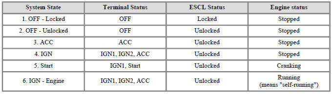
Referring to the terminals, the system states described in the table above are same as those one found in a system based on a mechanical ignition switch. The one of distinction with Mechanical-Ignition-Switch based system is that the BES system allows specific transition from (OFF) to (START) without going through (ACC) and (IGN) states.
System states in virgin mode
The BES System can be set in 5 different states (OFF locked is not available
in virgin mode), depending on the status of the
terminals, ESCL and Engine status: 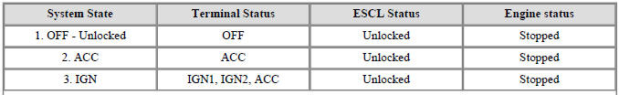
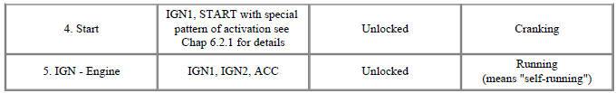
Referring to the terminals, the system states described in the table above are same as those one found in a system based on a mechanical ignition switch. The one of distinction with Mechanical-Ignition-Switch based system is that the BES system allows specific transition from (OFF) to (START) without going through (ACC) and (IGN) states.
READ NEXT:
 Start/Stop Button | ESCL (Electronic Steering Column Lock)
Start/Stop Button Repair procedures
Removal
Disconnect the negative (-) battery terminal.
Remove the crash pad garnish assembly (RH). (Refer to Body - "Crash Pad Garnish (RH)")
Remove the start/stop button.
(1) Push
Electro Chromic Inside Rear View Mirror
Schematic Diagrams
Description
The ECM (Electro Chromatic inside rear view Mirror) is one that automatically
dims to protect the
driver's eyes when it senses light reflecting from the car behind. The sensor in
the mirror detects the
brigh
SEE MORE:
Tire chains (Kia NIRO Hybrid)
wire-type
fabric-type
Since the sidewalls of radial tires are
thinner, they can be damaged by
mounting some types of snow chains on
them. Therefore, the use of snow tires is
recommended instead of snow chains.
Do not mount tire chains
ESP OFF Switch
ESP OFF Switch Components and components location
ESP OFF swtich
Description
The ESP OFF switch is for the user to turn off the ESP system.
The ESP OFF lamp is on when ESP OFF switch is engaged.
Removal
Turn ignition switch OF
Categories
- Home
- KIA Niro EV, Hybrid - Second generation - (SG2) (2021-2024) - Owner's manual
- Kia Niro - First generation - (DE) (2017-2022) - Service and Repair Manual
- Contact Us