KIA Niro: Clutch Actuator Assembly
Components
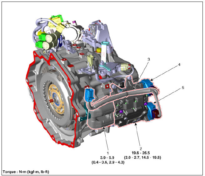
- Fork cover
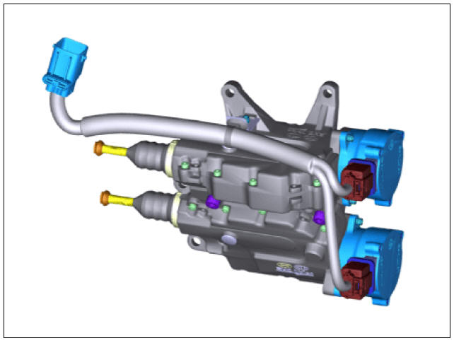
- Clutch actuator assembly
- Extension connector
- Motor 1 (Odd)
- Motor 2 (Even)
Specifications
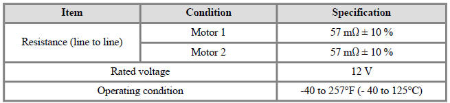
Description
The clutch actuator uses signals from the Transmission Control Module (TCM) to control the clutch.
Schematic Diagrams
Clutch Actuator Assembly Repair procedures
Removal
Clutch Actuator Assembly Repair procedures
- Remove the under cover.
(Refer to Engine Mechanical System - "Engine Room Under Cover")
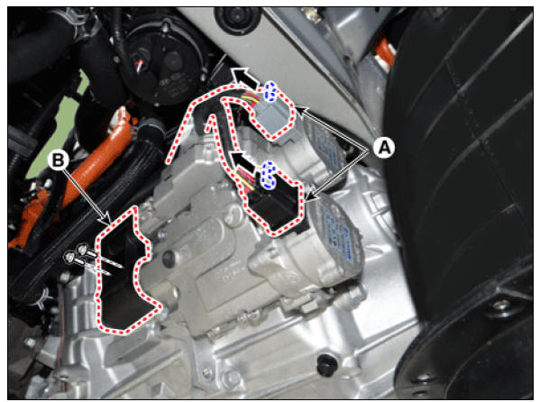
- Disconect the clutch actuator connector (A) and then remove the fork cover (B).
Tightening torque : 3.9 - 5.9 N*m (0.4 - 0.6 kgf*m, 2.9 - 4.3 lb*ft)
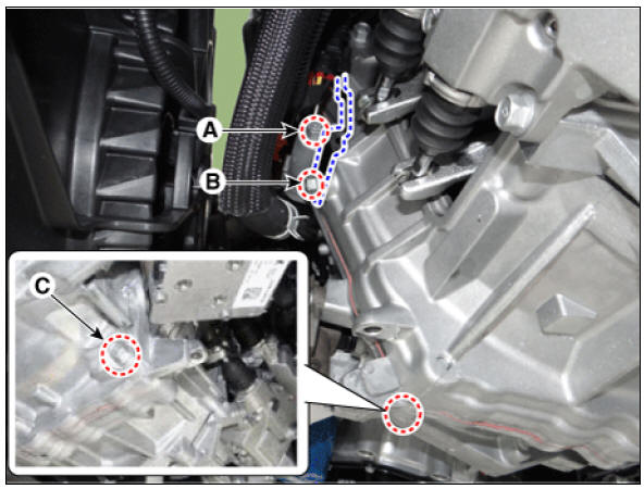
- Install the special service tool (09430-G2100).
(1) Loosen the bolts (A, B , C).
Tightening torque : (A, C) 42.2 - 53.9 N*m (4.3 - 5.5 kgf*m, 31.1 - 39.8 lb*ft) (B) 9.8 - 11.8 N*m (1.0 - 1.2 kgf*m, 7.2 - 8.7 lb*ft)
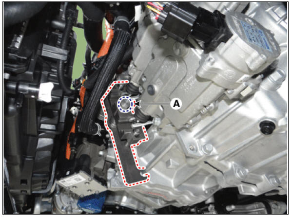
- Fix the clutch fork by rotating a bolt (A) after installing special service tool (09430-G2100).
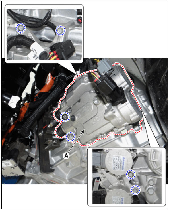
- Remove the clutch actuator assembly (A) after loosening the bolts.
Tightening torque : 19.6 - 26.5 N*m (2.0 - 2.7 kgf*m, 14.5 - 19.5 lb*ft)
READ NEXT:
 Clutch Actuator Motor
Remove the under cover.
(Refer to Engine Mechanical System - "Engine Room Under Cover")
Remove the front wheel guard (LH).
(Refer to Body - "Front Wheel Guard")
Disconect the clutch actuator connector (A).
Motor
Gear Actuator Assembly, Repair procedures
Component Location
Gear actuator assembly
Shift motor 2 (Even)
Shift motor 1 (Odd)
Select solenoid 2 (Even)
Select solenoid 1 (Odd)
Specification
Gear Actuator Assembly Description and operation
Description
SEE MORE:
Windshield Glass / Installation
Warning
When replacing the windshield glass fitted with
the front camera, be sure to replace it with the
replacement windshield glass fitted with the coupler. If attaching the coupler
on the windshield
glass without coupler, the front camera m
Hybrid Motor Control System
Description
The Hybrid Power Control Unit (HPCU), composed of various components, is
the core device among the Power Electronics
devices that acts as the brain.
It comprises of the Hybrid Control Unit (HCU), an inverter Motor Control
Un
Categories
- Home
- KIA Niro EV, Hybrid - Second generation - (SG2) (2021-2024) - Owner's manual
- Kia Niro - First generation - (DE) (2017-2022) - Service and Repair Manual
- Contact Us