KIA Niro: Connecting Rod
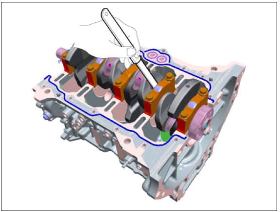
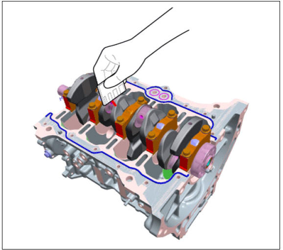
- Check the connecting rod side clearance.
Using a feeler gauge, measure the end play while moving the connecting rod back and forth.
- If out-of-tolerance, install a new connecting rod.
- If still out-of-tolerance, replace the crankshaft.
Side clearance : Standard: 0.10 - 0.25 mm (0.0039 - 0.0098 in.)
- Check the connecting rod bearing oil clearance.
(1) Check that the match marks on the connecting rod and cap are aligned to ensure correct reassembly.
(2) Remove 2 connecting rod cap bolts.
(3) Remove the connecting rod cap and lower bearing.
(4) Clean the crank pin and bearing.
(5) Place a plastigage across the crankshaft pin journal.
(6) Reinstall the lower bearing and cap, and torque the bolts.
Tightening torque : (10.8 - 14.7 N*m (1.1 - 1.5 kgf*m, 8.0 - 10.9 lb*ft)) + (88 - 92º)
Warning
- Always use new connecting rod cap bolts. Connecting rod cap bolts are torque-to-yield bolts designed to be permanently elongated beyond the state of elasticity when torqued. Reusing the removing bolts can cause the bolts to break or fail to maintain clamping force.
- Do not turn the crankshaft.
(7) Remove the connecting rod cap and lower bearing.
(8) Measure the width of the plastigage at its widest point.
Oil clearance
Standard ;
0.018 - 0.036 mm (0.0007 - 0.0014 in.)
Limit :
0.030 - 0.056 mm (0.0012 - 0.0022 in.)
(9) If the measurement from the plastigage is too wide or too narrow, remove the upper and lower bearing and then install new bearings with the same color mark. Recheck the oil clearance.
Warning
Do not file, shim, or scrape the bearings or the caps to adjust clearance.
(10) If the plastigage shows the clearance is still incorrect, try the next larger or smaller bearing. Recheck the oil clearance.
Warning
- If the proper clearance cannot be obtained by using the appropriate larger or smaller bearings, replace the crankshaft and repeat the check procedure.
- If the marks are indecipherable due to an accumulation of dirt and dust, clean with solvent or detergent instead of scrubbing them with a wire brush or scraper.
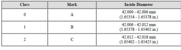
Connecting Rod Identification Mark
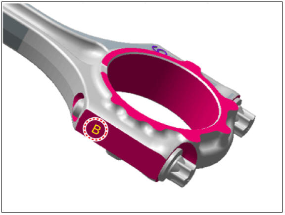
Connecting Rod Specifications
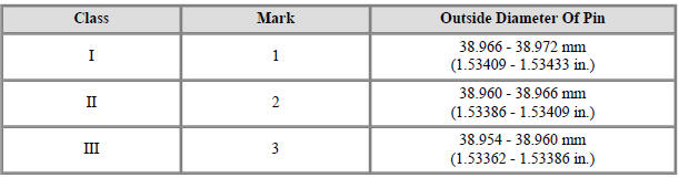
Crankshaft Pin Identification Mark
Warning
Conform to the stamping order in the direction of the arrow from #1.
Crankshaft Specifications
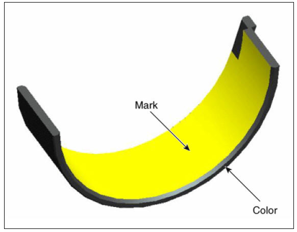
Connecting Rod Bearing Identification Mark
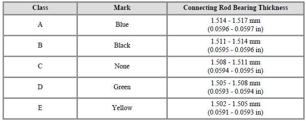
Connecting Rod Bearing Specifications
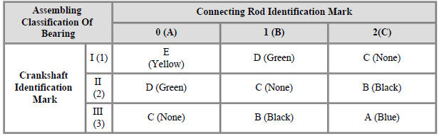
(11) Select a connecting rod bearing using selection chart.
Selection Chart For Connecting Rod Bearings
- Check the connecting rods.
(1) When reinstalling, make sure that cylinder numbers marked on the connecting rod and cap match during disassembly. When a new connecting rod is installed, make sure that the notches for holding the bearing in place are on the same side.
(2) Replace the connecting rod if it is damaged on the thrust faces at either end. Also if step wear or a severely rough surface of the inside diameter of the small end is apparent, the rod must be replaced as well.
(3) Using a connecting rod aligning tool, check the rod for bend and twist. If the measured value is close to the repair limit, correct the rod by a press. Any connecting rod that has been severely bent or distorted should be replaced.
Allowable bend of connecting rod : 0.05 mm (0.0020 in.) or less for 100 mm (3.94 in.) Allowable twist of connecting rod : 0.10 mm (0.0039 in.) or less for 100 mm (3.94 in.)
Warning
When the connecting rods are installed without bearings, there should be no difference on side surface.
READ NEXT:
 Piston, rings
Clean piston.
(1) Using a gasket scraper, remove the carbon from the piston top.
(2) Using a groove cleaning tool or broken ring, clean the piston ring grooves.
(3) Using solvent and a brush, thoroughly clean the piston.
Warning
Do not
Piston Pins
Measure the diameter of the piston pin.
Piston pin diameter :
17.997 - 18.000 mm (0.70854 - 0.70866 in.)
Measure the piston pin-to-piston clearance.
Piston pin-to-piston clearance :
0.005 - 0.012 mm (0.00020 - 0.00047 in.)
Chec
SEE MORE:
Seatback pocket
Seatback pocket
USB charger
WARNING
Loose objects in the driver's foot area
could interfere with the operation of
the foot pedals, possibly causing an
accident.
When you return the seatback to its
upright position, hold
Inverter kit / Body kit
Remove the battery (-) cable.
Disconnect the high voltage circuit. (Refer to Generals)
Use the recovery/reproduction/charging device to recover the coolant.
Warning
When removing the connector between the vehicle and the
compressor,
Categories
- Home
- KIA Niro EV, Hybrid - Second generation - (SG2) (2021-2024) - Owner's manual
- Kia Niro - First generation - (DE) (2017-2022) - Service and Repair Manual
- Contact Us