KIA Niro: Piston and Connecting Rod Repair procedures
Disassembly
Warning
- Be sure to read and follow the "General Safety Information and Caution" before doing any work related with the high voltage system. Failure to follow the safety instructions may result in serious electrical injuries.
- Be sure to shut off the high voltage circuit according to the "High Voltage Shut-off Procedures" before doing any work related with the high voltage system to avoid serious electrical injuries.
Warning
- Turn the crankshaft pulley so that the No.1 piston is at TDC (Top dead center).
- Use fender covers to avoid damaging painted surfaces.
- To avoid damaging the cylinder head, wait until the engine coolant temperature drops below normal temperature before removing it.
- When handling a metal gasket, be careful not to fold the gasket or damage the contact surface of the gasket.
- To avoid damage, unplug the wiring connectors carefully while holding the connector portion.
Warning
Mark all wiring and hoses to avoid misconnection.
- Shut off the high voltage circuit.
(Refer to Engine Mechanical System - "High Voltage Shut off Procedure")
- Remove the engine assembly from the vehicle.
(Refer to Engine and Transaxle Assembly - "Engine and Transaxle Assembly")
- Remove the dual clutch transmission.
(Refer to Double Clutch Transmission (DCT) - "Double Clutch Transmission Assembly")
- Install the engine to engine stand for disassembly.
- Remove the intake manifold.
(Refer to Intake and Exhaust System - "Intake Manifold")
- Remove the exhaust manifold.
(Refer to Intake and Exhaust System - "Exhaust Manifold")
- Remove the hybrid starter generator (HSG).
(Refer to Hybrid Motor System - "Hybrid Starter Generator (HSG)")
- Remove the timing chain.
(Refer to Timing System - "Timing Chain")
- Remove the Cylinder head assembly.
(Refer to Cylinder Head Assembly - "Cylinder Head")
- Remove the Fly Wheel.
(Refer to Cylinder Block - "Fly Wheel")
- Remove the thermostat.
(Refer to Cooling System - "Thermostat")
- Remove the water pump assembly.
(Refer to Cooling System - " Water Pump")
- Remove the A/C compressor.
(Refer to Heating, Ventilation Air conditioning -"Compressor")
- Remove the oil filter.
(Refer to Lubrication System - "Engine Oil")
- Remove the oil screen.
(Refer to Lubrication System - "Oil Pan")
- Remove the ladder frame mounting bolt.
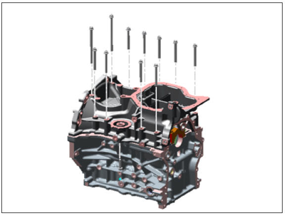
- Using the SST (09215-3C000) and remove the ladder frame (A).
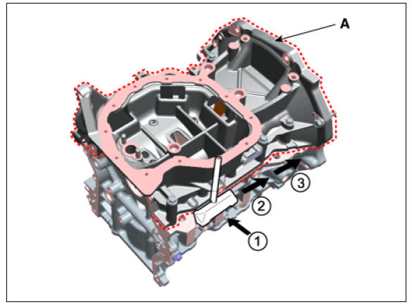
Warning
- Insert the SST between the ladder frame and the cylinder block by tapping it with a plastic hammer in the direction of ¬ arrow.
- fter tapping the SST with a plastic hammer along the direction of  arrow around more than 2/3 edge of the ladder frame, remove it from the cylinder block.
- Do not turn over the SST abruptly without tapping. It be result in damage of the SST.
- Check the connecting rod side clearance.
- Check the connecting rod bearing cap oil clearance.
- Remove the piston and connecting rod assembly.
(1) Using a ridge reamer, remove all the carbon from the top of the cylinder.
(2) Remove the connecting rod bearing caps (A).
(3) Push the piston and connecting rod assembly (B) with upper bearing through the top of the cylinder block.
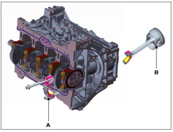
Warning
- Mark the connecting rod and bearing caps to be able to reassemble in the original position and direction.
- Keep the connecting rod and caps with the bearings assembled together.
- Arrange the piston and connecting rod assemblies in the correct order.
- Mark the piston and connecting rod assembly to be able to reassemble in the original position.
- Check fit between piston and piston pin.
Try to move the piston back and forth on the piston pin. If any movement is felt, replace the piston and pin as a set.
- Disassemble the piston rings.
(1) Using a piston ring expender, remove the two compression rings.
(2) Remove the two side rails and coil spring.
Warning
Arrange the piston rings in the correct order.
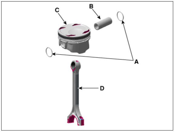
- Disassemble the connecting rod from the piston.
(1) Remove the snap ring (A) from the piston.
(2) Remove the piston pin (B) from the piston.
(3) Disassemble the piston (C) and connecting rod (D).
Inspection
READ NEXT:
 Connecting Rod
Check the connecting rod side clearance.
Using a feeler gauge, measure the end play while moving the connecting rod
back and forth.
If out-of-tolerance, install a new connecting rod.
If still out-of-tolerance, replace the crankshaft.
Piston, rings
Clean piston.
(1) Using a gasket scraper, remove the carbon from the piston top.
(2) Using a groove cleaning tool or broken ring, clean the piston ring grooves.
(3) Using solvent and a brush, thoroughly clean the piston.
Warning
Do not
SEE MORE:
Front Seat Belt Retractor | Height Adjuster
Front Seat Belt / Components And Components Location
Front seat belt retractor
Height adjuster
Rear seat belt retractor (side)
Rear seat belt retractor (center)
Front Seat Belt Retractor
Front seat belt retractor
Setting the power tailgate
Power tailgate opening speed
You can adjust the power tailgate opening
speed. Select the desired opening
speed (Fast / Slow) (Default setting is
Fast).
Operation
Instrument cluster (if equipped)
Select Settings → Door → Power
Tailgat
Categories
- Home
- KIA Niro EV, Hybrid - Second generation - (SG2) (2021-2024) - Owner's manual
- Kia Niro - First generation - (DE) (2017-2022) - Service and Repair Manual
- Contact Us