KIA Niro: Cooling Fan Repair procedures | Cooling Fan Assembly
Kia Niro - First generation - (DE) (2017-2022) - Service and Repair Manual / Engine Mechanical System / Cooling System / Cooling Fan Repair procedures | Cooling Fan Assembly
Cooling Fan Components and components location
Components
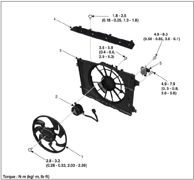
- Cooling fan
- Cooling fan motor
- Cooling fan shroud
- Air dam
- Cooling fan controller (PWM)
Description
Controls the cooling fan motor voltage depending on the duty output from the ECU (Freq.: 300Hz).
Signal from the ECU to the PWM (SI: 300Hz)
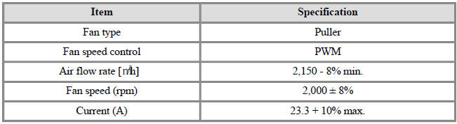
Specifications
Circuit Diagram
PWM Circuit Diagram
Cooling Fan Assembly
Removal and
Installation
- Disconnect the negative battery terminal.
- Remove the air cleaner and air duct A.
(Refer to Intake and Exhaust System - "Air Cleaner")
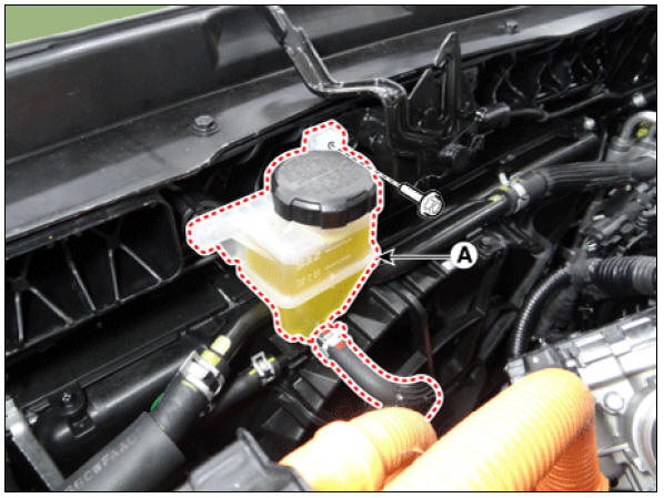
- Separate the engine clutch reservoir tank (A).
Tightening torque : 3.9 - 5.9 N*m (0.4 - 0.6 kgf*m, 2.9 - 4.3 lb*ft)
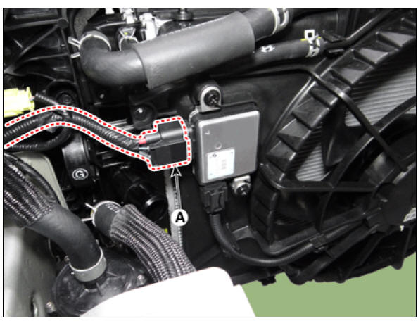
- Disconnect the cooling fan control module (PWM) connector (A).
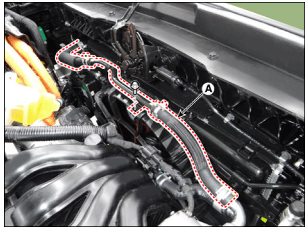
- Remove the hybrid starter generator coolant hose & pipe (A) from the cooling fan shroud.
Tightening torque : 7.8 - 11.8 N*m (0.8 - 1.2 kgf*m, 5.8 - 8.7 lb*ft)
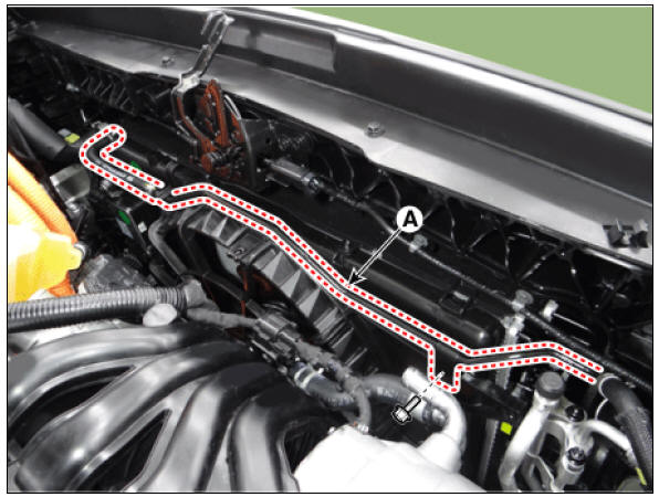
- Separate the radiator coolant pipe (A) from the cooling fan shroud.
Tightening torque : 7.8 - 11.8 N*m (0.8 - 1.2 kgf*m, 5.8 - 8.7 lb*ft)
- Remove the air dam (A).
Tightening torque : 1.8 - 2.5 N*m (0.18 - 0.25 kgf*m, 1.3 - 1.8 lb*ft)
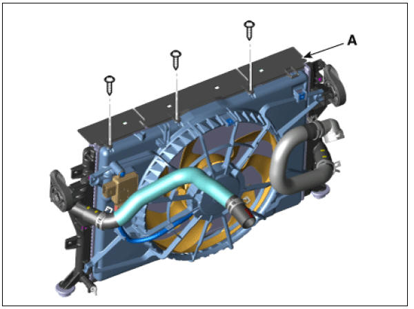
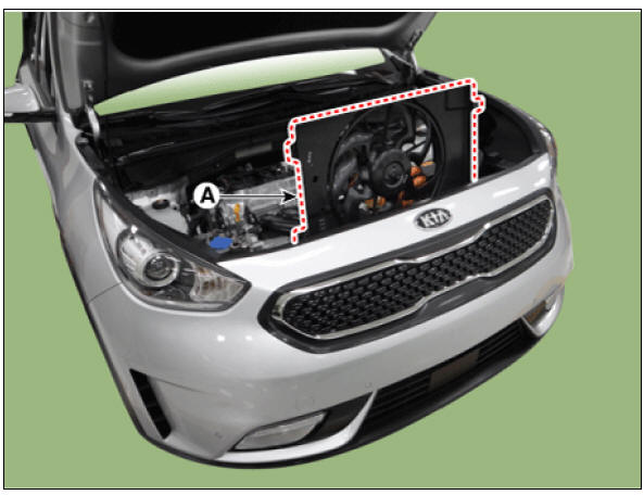
- Remove the cooling fan assembly (A).
Tightening torque : 4.9 - 8.3 N*m (0.5 - 0.8 kgf*m, 3.6 - 6.1 lb*ft)
- Install in the reverse order of removal.
READ NEXT:
 Cooling Fan Control Module (PWM) | Radiator
Disconnect the battery negative terminal.
Remove the air duct.
(Refer to Intake and Exhaust System - "Air Cleaner")
Disconnect the cooling fan control module (PWM) connector (A) and cooling fan motor
SEE MORE:
Sunroof / Repair Procedures
Adjustment
Inspect Glass Alignment
Inspect the step height between the roof panel (A) and the glass
weatherstrip (B) and then adjust it if
necessary.
Alignment adjustment
Standard value (mm(in.))
(1) Front edge : 0 mm (0 in.)
(2) Rear
Normal maintenance schedule - for Australia and New Zealand
The following maintenance services must be performed to ensure good emission
control and performance. Keep
receipts for all vehicle emission services to protect your warranty. Where both
mileage and time are shown, the frequency
of service is d
Categories
- Home
- KIA Niro EV, Hybrid - Second generation - (SG2) (2021-2024) - Owner's manual
- Kia Niro - First generation - (DE) (2017-2022) - Service and Repair Manual
- Contact Us