KIA Niro: Cylinder Head
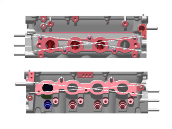
- Inspect for flatness.
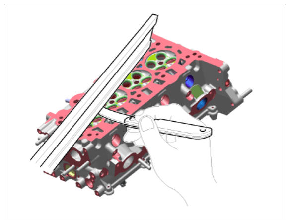
Using a precision straight edge and feeler gauge, measure the contacting surface of the cylinder block and check the manifolds for warpage.
If the flatness is greater than maximum, replace the cylinder head.
Flatness of cylinder head gasket surface :
Less than 0.05 mm (0.0020 in.) for total area Less than 0.02 mm (0.0008 in.) for a section of 100 mm (3.9370 in.) X 100 mm (3.9370 in.)
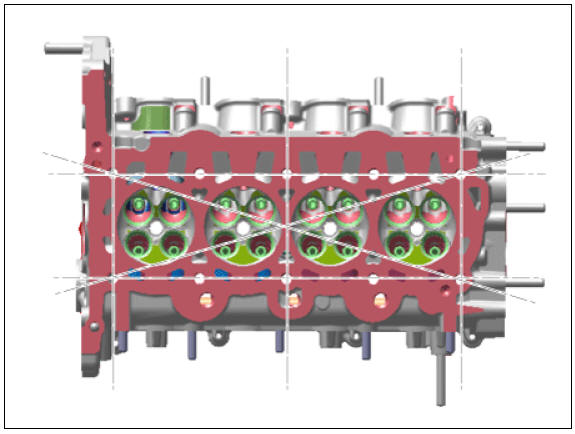
Flatness of manifold mounting surface : Less than 0.10 mm (0.0039 in.)
- Inspect for cracks.
Check the combustion chamber, intake ports, exhaust ports and cylinder block surface for cracks. If cracked, replace the cylinder head.
Valve And Valve Spring
- Inspect valve stems and valve guides.
(1) Using a caliper gauge, measure the inside diameter of the valve guide.
Valve guide inner diameter :
Intake : 5.500 - 5.512 mm (0.21654 - 0.21701 in.)
Exhaust : 5.500 - 5.512 mm (0.21654 - 0.21701 in.)
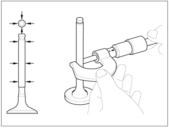
(2) Using a micrometer, measure the diameter of the valve stem.
Valve stem outer diameter :
Intake : 5.465 - 5.480 mm (0.21516 - 0.21575 in.)
Exhaust : 5.458 - 5.470 mm (0.21488 - 0.21535 in.)
(3) Subtract the valve stem diameter measurement from the valve guide inside diameter measurement.
If the clearance is greater than specification, replace the valve or the cylinder head.
Valve stem-to-guide clearance :
(Standard)
Intake : 0.020 - 0.047 mm (0.00079 - 0.00185 in.)
Exhaust : 0.030 - 0.044 mm (0.00118 - 0.00252 in.)
- Inspect the valves.
(1) Check that the valve is ground to the correct valve face angle.
(2) Check the surface of the valve for wear.
If the valve face is worn, replace the valve.
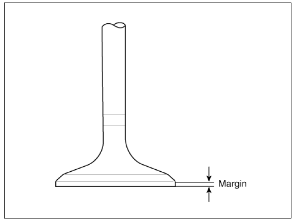
(3) Check the valve head margin thickness.
If the margin thickness is less than specification, replace the valve.
Margin
(Standard)
Intake : 1.35 - 1.65 mm (0.0531 - 0.0650 in.)
Exhaust : 1.60 - 1.90 mm (0.0630 - 0.0748 in.)
(4) Check the valve length.
Valve length :
Intake: 100.94 mm (3.9740 in.)
Exhaust: 101.09 mm (3.9740 in.)
(5) Check the surface of the valve stem tip for wear.
If the valve stem tip is worn, replace the valve.
- Inspect the valve seats and the valve guides.
(1) Check the valve seat for evidence of overheating and improper contact with the valve face.
If the valve seat is worn, replace the cylinder head.
(2) Check the valve guide for wear. If the valve guide is worn, replace the cylinder head.
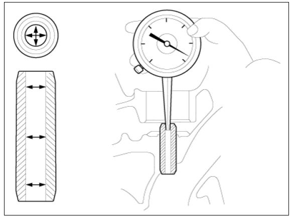
- Inspect the valve springs
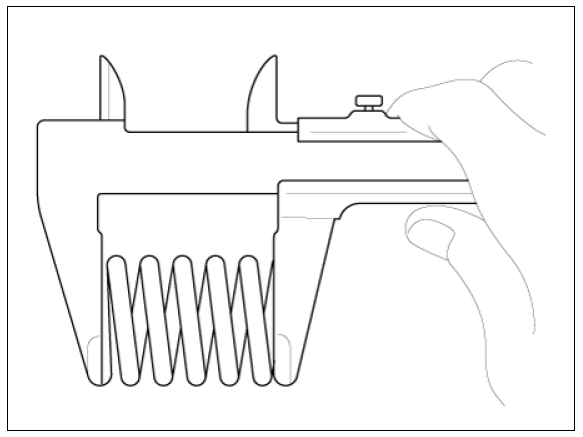
(1) Using a steel square, measure the out-of-square of valve spring.
(2) Using a vernier calipers, measure the free length of valve spring.
If the free length is not as specified, replace the valve spring.
Valve spring :
(Standard)
Free height:
50.27 mm (1.9791 in.)
Load :
16.4 +- 0.8 kgf*m / 35.5 mm (36.16 +- 1.76 lb*f / 1.3976 in.) 26.0 +- 0.9 kgf*m / 22.7 mm (57.32 +- 1.98 lb*f / 0.8937 in.)
Out-of-square :
Less than 1.5º
READ NEXT:
 HLA (Hydraulic Lash Adjuster)
With the HLA filled with engine oil, hold A and press B by hand.
If B moves, replace the HLA.
Reassembly
Warning
Thoroughly clean all parts to be assembled.
Before installing the parts, apply fresh engine oil to all
sliding
Drive Belt / Idler Repair procedures
Drive Belt Repair procedures
Removal
Remove the engine room under cover.
(Refer to Engine and Transaxle Assembly - "Engine Room Under Cover")
Remove the drive belt.
(1) Using the wrench, turning the mechanical tensioner (A) co
SEE MORE:
Floor Carpet
Floor Carpet / Repair Procedures
Replacement
Warning
Put on gloves to protect your hands.
Warning
Use a plastic panel removal tool to remove interior trim pieces
without marring the surface.
Be careful not to bend or scratch the tr
Engine compartment (Kia Niro Hybrid only)
Smartstream G1.6 GDi HEV
Smartstream G1.6 GDi PHEV
Engine coolant reservoir
Brake fluid reservoir
Air cleaner
Engine oil filler cap
Engine oil dipstick
Windshield washer fluid reservoir
Fuse box
Inverter coolant reservoir
Categories
- Home
- KIA Niro EV, Hybrid - Second generation - (SG2) (2021-2024) - Owner's manual
- Kia Niro - First generation - (DE) (2017-2022) - Service and Repair Manual
- Contact Us