KIA Niro: Driver Airbag (DAB) Module and Clock Spring
Driver Airbag (DAB) Module and Clock Spring Description and operation
Description
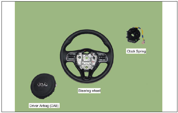
Driver Airbag (DAB) is installed in the steering wheel and electrically connected to SRSCM via the clock spring.
It protects the driver by deploying the airbag when frontal crash occurs. The SRSCM determines deployment of the Driver Airbag (DAB).
Warning
Never attempt to measure the circuit resistance of the airbag module (squib) even if you are using the specified tester. If the circuit resistance is measured with a tester, accidental airbag deployment will result in serious personal injury.
Driver Airbag (DAB) Module and Clock Spring Components and components
Driver Airbag (DAB) Module and Clock Spring Repair procedures
Inspection
Air bag module
If any improper parts are found during the following inspection, replace the airbag module with a new one.
Warning
Never attempt to measure the circuit resistance of the airbag module (squib) even if you are using the specified tester. If the circuit resistance is measured with a tester, accidental airbag deployment will result in serious personal injury.
- Check pad cover for dents, cracks or deformities.
- Check the airbag module for denting, cracking or deformities.
- Check hooks and connectors for damage, terminals for deformities, and harness for binds.
- Check airbag inflator case for dents, cracks or deformities
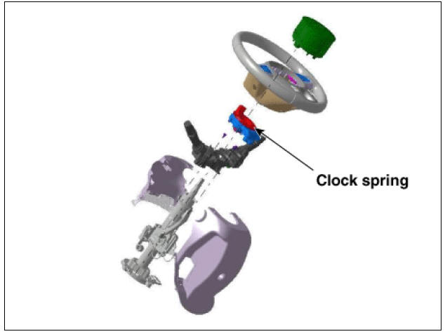
Clock Spring
- If, as a result of the following checks, even one abnormality is discovered, replace the clock spring with a new one.
- Check connectors and protective tube for damage, and terminals for deformities.
Removal
- Set the front tires straight-ahead before assembling the steering wheel.
Warning
If the steering wheel and the front tires are not set straight ahead together, it may affect the number of circulation of steering wheel and damage the cable inside the clock spring.
- Disconnect the battery negative terminal, and wait for at least 30 seconds before beginning to work.
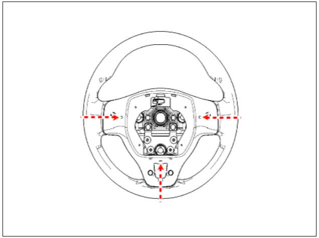
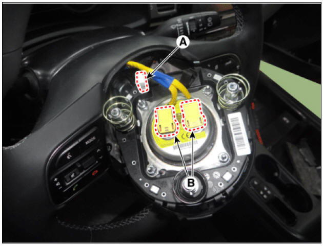
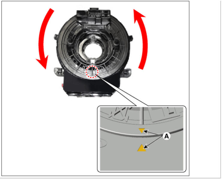
- While turning the steering wheel to left and right, press the parts marked A (3 red dotted circles) under the steering wheel and then remove the airbag module.
- Disconnect the air bag connector (A) and horn connector (B).
Warning
The removed airbag module should be stored in a clean, dry place with the pad cover facing up.
- Remove the steering wheel.
(Refer to Steering System - "Steering wheel")
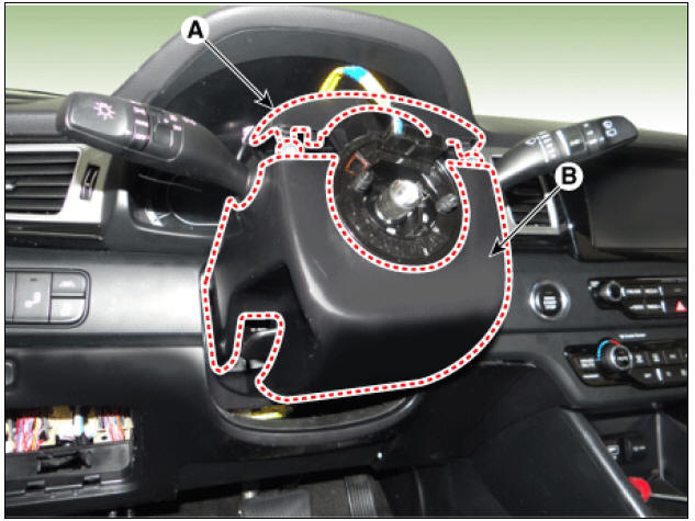
- Remove the upper steering wheel column shroud (A).
- Loosen the screws and remove the lower shroud (B).
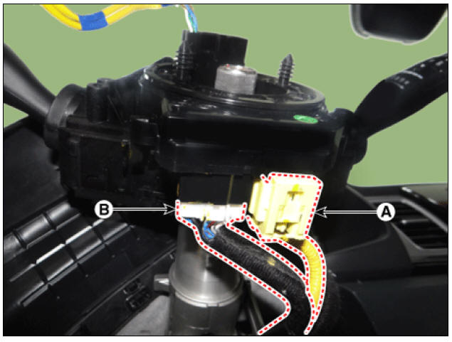
- Separate clock spring wiring harness connector (A) to the horn wiring harness connector (B) in a clock spring.
Installation
- Set the front tires straight-ahead before assembling the steering wheel.
Warning
If the steering wheel and the front tires are not set straight ahead together, it may affect the number of circulation of steering wheel and damage the cable inside the clock spring.
- Make sure the cable is disconnected (-) Battery
Warning
After disconnecting the cables, wait at least 30 seconds.
- Turn the vehicle in neutral before assembling the clock spring
Warning
If the steering wheel and the front tires are not set straight ahead together, it may affect the number of circulation of steering wheel and damage the cable inside the clock spring. .
Damage to the clock spring may cause electric malfunctions in airbag warning lamp, horn, handsfree, auto cruise, heated wire and heated steering, and noise from turning the steering wheel.
Warning
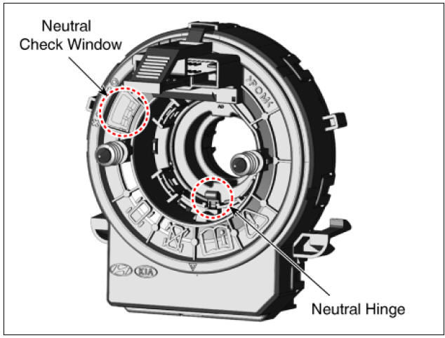
Manually adjust the clock spring neutral way
1) Push the auto-lock button placed at the 6 o'clock position and
turn it clockwise until it stops. 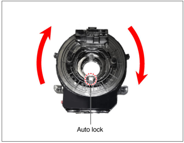
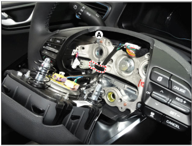
2) Push the auto-lock button placed at the 6 o'clock position and
turn approximately 2 rotations
counter-clockwise to align with the neutral mark (A).
- Check the neutral state of the clock spring is attached to the steering column.
- Connect the clock spring harness connector and horn harness connector to the clock spring.
Warning
Connect the connector until the lock 'clicks'.
- Fit the steering column shroud panel.
(Refer to Body - see "steering column shroud panel")
- Fit the steering wheel.
(Refer to Steering system - see "steering wheel")
- Connect the driver airbag connector is equipped with a driver's airbag module.
Warning
- Connect the connector until the lock 'clicks'.
- By using the band clip (A), fix the airbag and horn wirings inside the steering wheel.
- Connect the Driver Airbag (DAB) module connector and horn connector, and then install the Driver Airbag (DAB) module on the steering wheel
- Assemble the wire while pressing the airbag module towards the
center.
- Connect the cable from the back (-) the battery.
- Check if the steering wheel remote control, airbag system and horn are normally operating after turning the handle all the way left and right when installing air bag module is done.
Warning
Turn the ignition switch ON; the SRS indicator light should be turned on for about six seconds and then go off
READ NEXT:
 Passenger Airbag (PAB) and Side Airbag (SAB)
Passenger Airbag (PAB) Module Description and operation
Description
The passenger airbag (PAB) is installed inside the crash pad and protects the front passenger in the event of a frontal crash. The SRSCM determines if and when to deploy the PAB.
Curtain Airbag (CAB)
Description
Curtain airbags are installed inside the headliner (LH and RH) and protect
the driver and passenger
from danger when side crash occurs. The SRSCM determines deployment of curtain
airbag by using
side impact sensor (SIS) signal.
Wa
SEE MORE:
Sunroof Guide
Replacement
Remove the sunroof assembly.
(Refer to Sunroof - "Sunroof Assembly")
Remove the sunroof sunshade.
(Refer to Sunroof - "Sunroof Sunshade")
Push down the slide and remove the drip link assembly (A).
Limitations of Remote Smart
Parking Assist
In the following circumstances, Remote
Smart Parking Assist performance to
park or exit the vehicle may be limited,
there may be a risk of collision, or
Remote Smart Parking Assist may turn
off. Park or exit the vehicle manually if
necessary.
Categories
- Home
- KIA Niro EV, Hybrid - Second generation - (SG2) (2021-2024) - Owner's manual
- Kia Niro - First generation - (DE) (2017-2022) - Service and Repair Manual
- Contact Us