KIA Niro: Battery Pack Assembly Repair procedures
Kia Niro - First generation - (DE) (2017-2022) - Service and Repair Manual / Service Highlight / High Voltage Battery System / Battery Pack Assembly Repair procedures
Disassembly
Warning
- Be sure to read and follow the "General Safety Information and Caution" before doing any work related with the high voltage system. Failure to follow the safety instructions may result in serious electrical injuries.
- Be sure to shut off the high voltage before doing any work related with the high voltage system(Refer to "High Voltage Shut-off Procedure"). Failure to follow the safety instructions may result in serious electrical injuries.
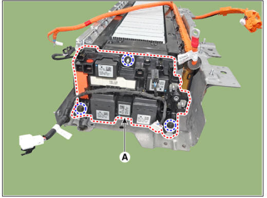
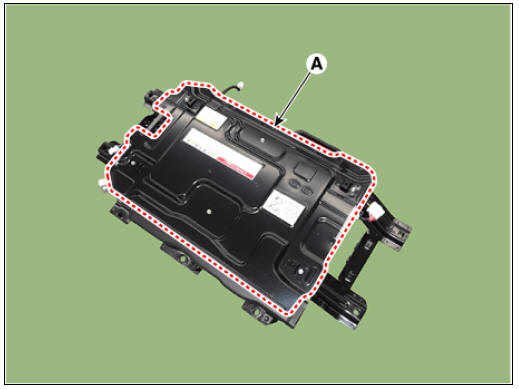
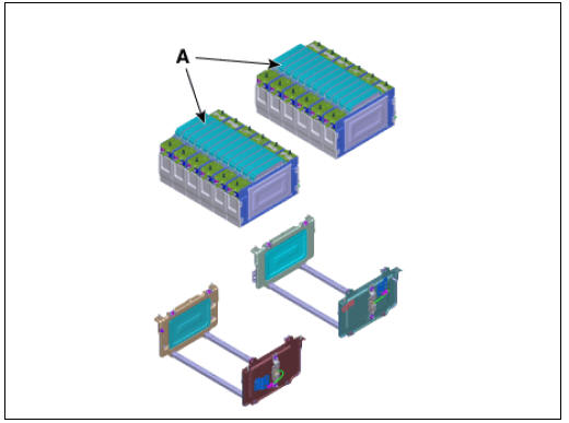
- Remove the high voltage battery front cover (A).
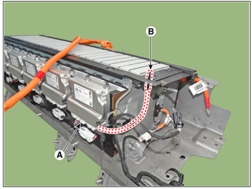
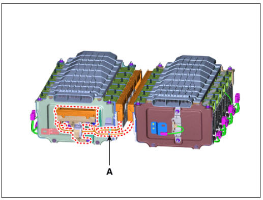
- Disconnect the OBC relay connector (A) and PRA connector (B).
- Remove the high voltage cable cover (A).
- Disconnect the battery current sensor connector (A).
- Disconnect the high voltage power cable (+) terminal (A) and (-) terminal (B) after loosening the mounting nuts.
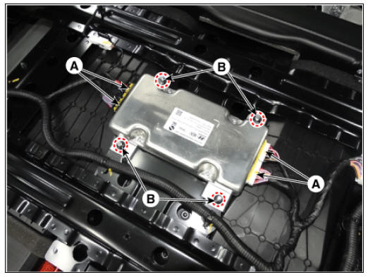
- Remove the power relay assembly (A) after loosening the mounting bolts and nuts.
- Disconnect the inlet temperature sensor connector (A) and then remove the inlet temperature sensor (B).
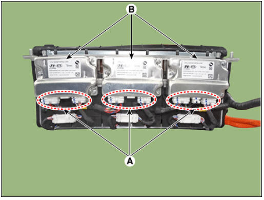
- Disconnect the cell monitoring unit connector (A).
- Remove the cell monitoring unit (CMU) (B) after loosening the mounting nuts and screw.
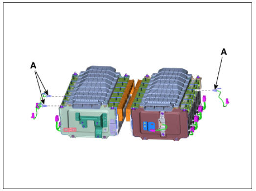
- Remove the high voltage cable (B) after loosening the ground bolts (A).
- Remove the battery temperature sensor (A).
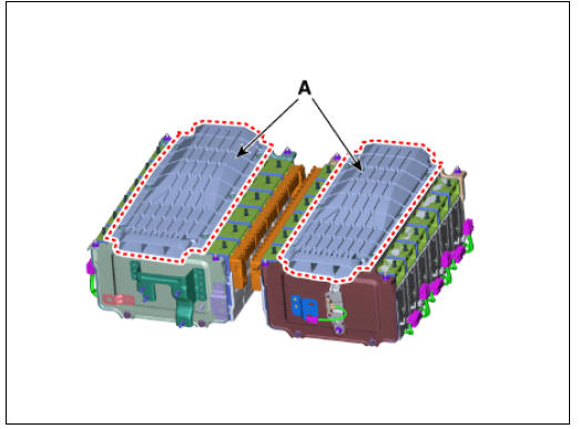
- Remove the air duct (A).
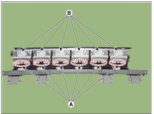
- Remove the bus bar (A) after loosening the mounting nuts.
- Remove the cell monitoring unit bracket (A) after loosening the mounting nuts.
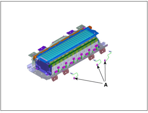
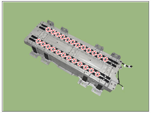
- Remove the battery module mounting nuts.
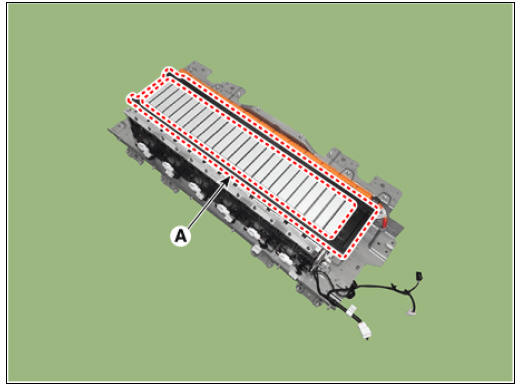
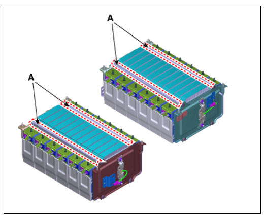
- Remove the main battery pack support bar (A).
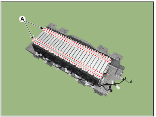
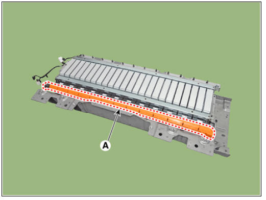
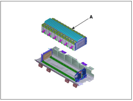
- Remove the sub high voltage battery module (A) from the battery plate.
Sub Battery Pack Assembly
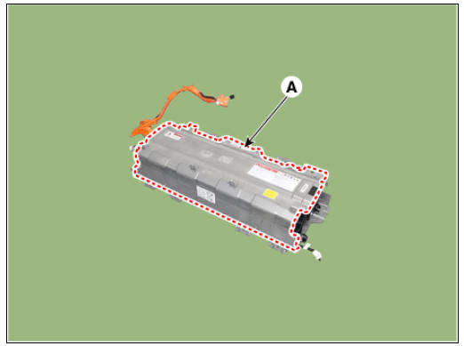
- Remove the high voltage battery cover (A) after loosening the bolts.
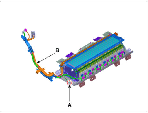
- Disconnect the BMS connector (A).
- Remove the BMS after loosening the bolts (B).
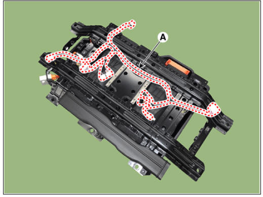
- Remove the BMS wiring harness (A).
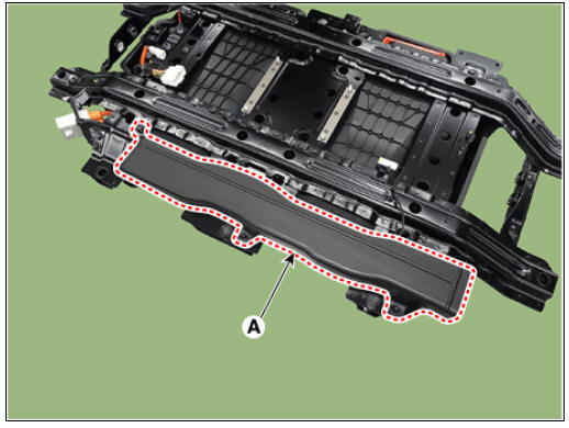
- Remove the outlet duct (A).
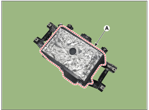
- Remove the watertight case (A) after loosening the bolts.
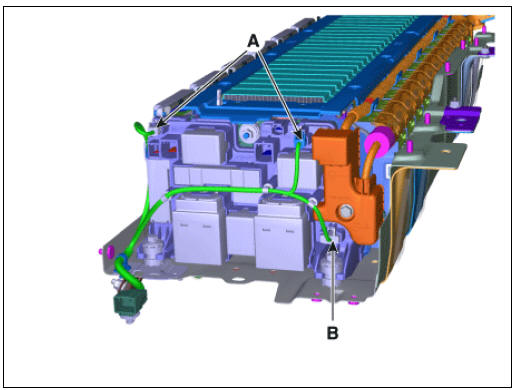
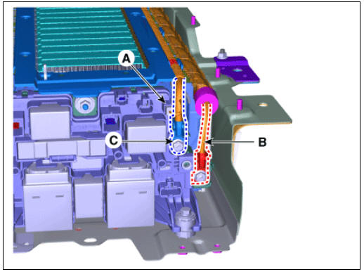
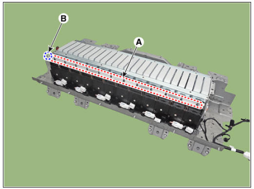
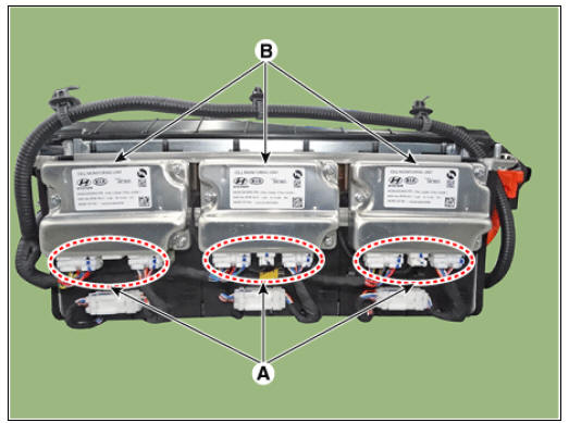
- Disconnect the cell monitoring unit connector (A).
- Remove the cell monitoring unit (B) after loosening the screw.
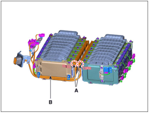
- Remove the high voltage cable (B) after loosening the nuts (A).
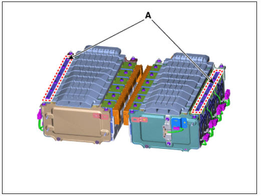
- Remove the cell monitoring unit bracket (A) after loosening the nuts.
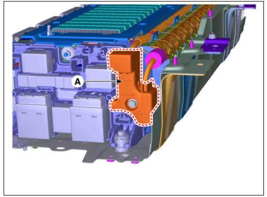
- Remove the main fuse assembly (A) after loosening the nuts.
- Remove the battery temperature sensor (A).
- Remove the air duct (A).
- Remove the sub battery pack support bar (A).
- Remove the sub high voltage battery module (A) from the battery plate.
Reassembly
Warning
- Be sure to read and follow the "General Safety Information and Caution" before doing any work related with the high voltage system. Failure to follow the safety instructions may result in serious electrical injuries.
- Be sure to shut off the high voltage before doing any work related with the high voltage system(Refer to "High Voltage Shut-off Procedure"). Failure to follow the safety instructions may result in serious electrical injuries.
- Install the battery pack assembly in the reverse order of removal.
READ NEXT:
 Battery Pack Assembly Troubleshooting Chart
Inspection
Warning
For SOC check, refer to "SOC Inspection"
For voltage check, refer to "Battery Voltage Inspection"
For battery voltage sensing circuit, refer to "Voltage Sensing
Circuit Inspection"
Fo
Power Relay Assembly (PRA)
PRA Operation Sequence
Description
The Power Relay Assembly (PRA) consists of the positive and negative main
relays, pre-charge relay, pre-charge resistor and
battery current sensor. It is located inside the battery pack assembly and
controls
Main High/ Sub High Voltage Battery
Main High Voltage Battery
Component Location
Power Relay Assembly (PRA)
Cell Monitoring Unit (CMU)
Battery Temperature Sensor
Runaway Arresting Device (RAD)
Warning
Main Relays (Positive, Negative), Pre-Charge Relay, Pre-Charge
R
SEE MORE:
Crash Pad Main Lower Panel
Crash pad main lower panel
Replacement
Warning
Put on gloves to protect your hands.
Warning
Use a plastic panel removal tool to remove interior trim pieces
without marring the surface.
Be careful not to bend or scratch the trim
Rear Door / Repair Procedures
Rear door trim
Rear door delta inner cover
Rear door panel & module
Rear door delta lower run & channel
Rear door side weatherstrip
Rear door body side weatherstrip
Rear door window glass run
Rear door delta moulding
Rear
Categories
- Home
- KIA Niro EV, Hybrid - Second generation - (SG2) (2021-2024) - Owner's manual
- Kia Niro - First generation - (DE) (2017-2022) - Service and Repair Manual
- Contact Us