KIA Niro: Power Relay Assembly (PRA)
PRA Operation Sequence
Description
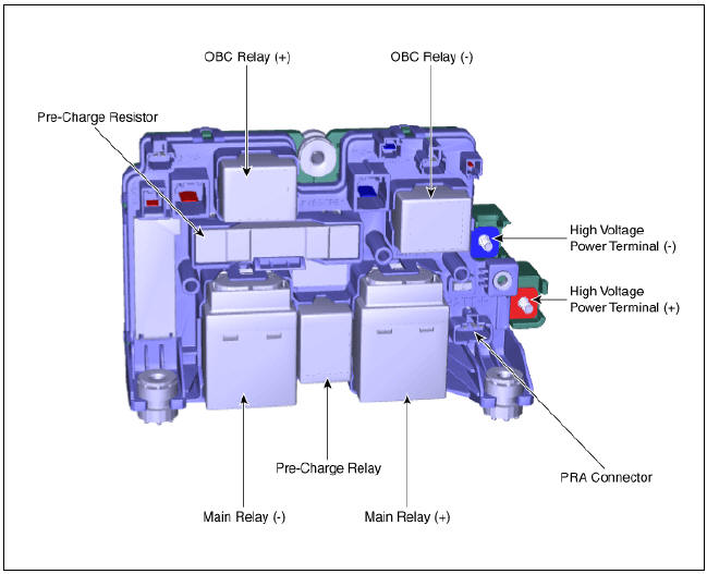
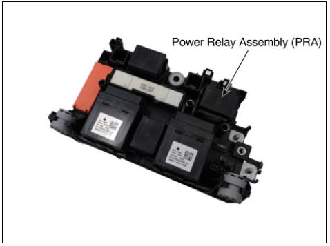
The Power Relay Assembly (PRA) consists of the positive and negative main relays, pre-charge relay, pre-charge resistor and battery current sensor. It is located inside the battery pack assembly and controls the high voltage power circuit between the high voltage battery and inverter by the control signal of BMS ECU.
PRA Operation Sequence
High Voltage Battery System / Repair Procedures
Removal
Warning
- Be sure to read and follow the "General Safety Information and Caution" before doing any work related with the high voltage system. Failure to follow the safety instructions may result in serious electrical injuries.
- Be sure to read and follow the "High Voltage Shut-off Procedures" before doing any work related with the high voltage system. Failure to follow the safety instructions may result in serious electrical injuries.
- Shut off the high voltage.
(Refer to "High voltage Shut-off Procedures")
- Remove the rear seat cushion.
(Refer to Body - "Rear Seat Assembly")
- Remove the rear door scuff trim.
(Refer to Body - "Door Scuff Trim")
- Remove the inlet cooling duct.
(Refer to High Voltage Battery Cooling System - "Cooling Duct")
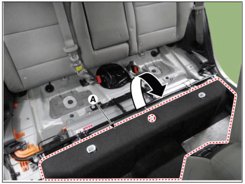
- Open the floor carpet (A) to the arrow direction.
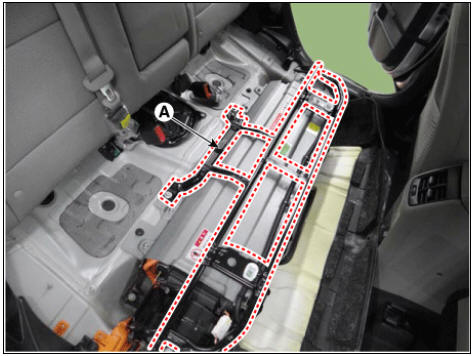
- Remove the upper frame (A) after loosening the mounting bolts and nuts.
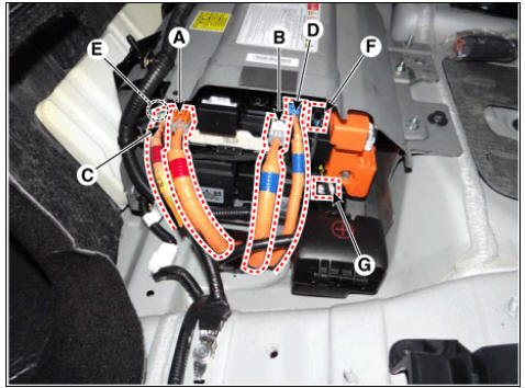
- Disconnect the connectors in the illustration below.
- Inverter power connector (+)
- Inverter power connector (-)
- OBC power connector (+)
- OBC power connector (-)
- OBC relay connector (+)
- OBC relay connector (-)
- PRA relay connector
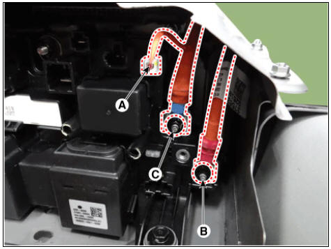
- Disconnect the battery current sensor connector (A).
- Disconnect the high voltage power cable (+) terminal (B) and (-) terminal (C).
High voltage power cable terminal tightening nut : 7.8 - 11.8 N.m (0.8 - 1.2 kgf.m, 5.8 - 8.7 lb-ft)
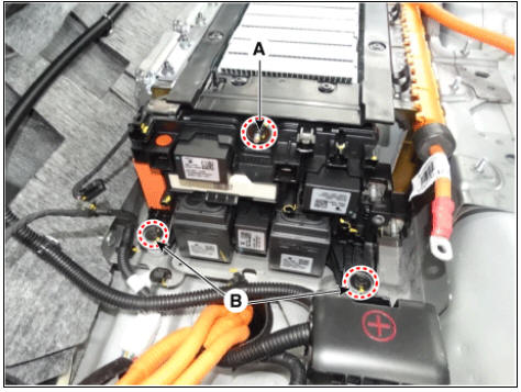
- Remove the power relay assembly (RPA) after loosening the mounting nut (A) and bolt (B).
PRA mounting nut : 7.8 - 11.8 N.m (0.8 - 1.2 kgf.m, 5.8 - 8.7 lb-ft)
Installation
Warning
- Be sure to read and follow the "General Safety Information and Caution" before doing any work related with the high voltage system. Failure to follow the safety instructions may result in serious electrical injuries.
- Be sure to read and follow the "High Voltage Shut-off Procedures" before doing any work related with the high voltage system. Failure to follow the safety instructions may result in serious electrical injuries.
- Install the power relay assembly in the reverse order of removal.
Description
The high voltage battery system consists of the BMS ECU (Battery Management
System ECU), Power
Relay Assembly (PRA), safety plug, battery temperature sensor, and battery
ambient sensor.
Especially the BMS ECU controls SOC (State Of Charge), power, cell balancing,
cooling and
Troubleshooting of the high voltage battery system.
The PRA includes main relays (positive, negative), pre-charge relay, pre-charge
resistor and battery
current sensor.
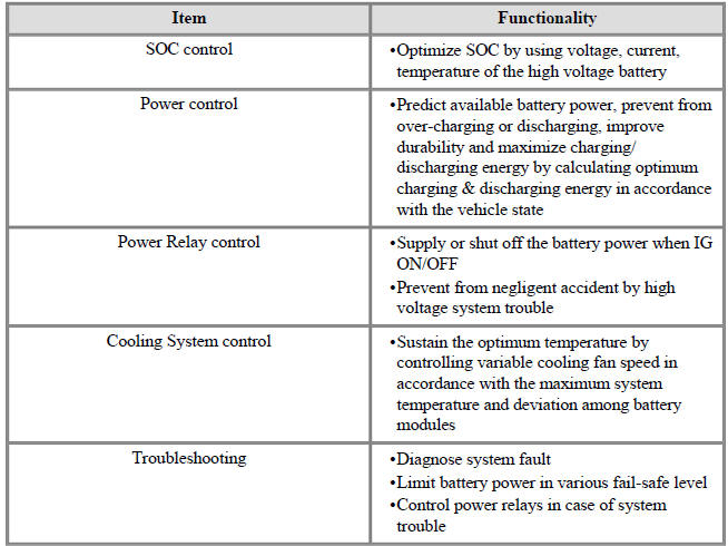
Main Functionalities
Warning
SOC (State Of Charge): available energy of the high voltage battery
- Main High/ Sub High Voltage Battery
- Sub High Voltage Battery - Removal
- Safety Plug Description and operation
- The Power Relay Assembly
READ NEXT:
 Main High/ Sub High Voltage Battery
Main High Voltage Battery
Component Location
Power Relay Assembly (PRA)
Cell Monitoring Unit (CMU)
Battery Temperature Sensor
Runaway Arresting Device (RAD)
Warning
Main Relays (Positive, Negative), Pre-Charge Relay, Pre-Charge
R
Sub High Voltage Battery - Removal
Warning
Be sure to read and follow the "General Safety Information and
Caution" before doing any work related
with the high voltage system. Failure to follow the safety instructions may
result in serious electrical
injuries.
Safety Plug Description and operation
Description
Safety Plug is installed on the rear side of the high voltage battery and it
can mechanically shut the
high voltage circuit off when servicing the high voltage system. (i.e. High
Voltage Battery, Power
Relay Assembly, HPCU, BMS ECU
SEE MORE:
Hazardous driving conditions
If driving conditions deteriorate due to
poor weather or road conditions, you
should pay even more attention than
usual.
When hazardous driving conditions are
encountered such as water, snow, ice,
mud, sand, or similar hazards, follow
these su
Rear Door / Repair Procedures
Rear door trim
Rear door delta inner cover
Rear door panel & module
Rear door delta lower run & channel
Rear door side weatherstrip
Rear door body side weatherstrip
Rear door window glass run
Rear door delta moulding
Rear
Categories
- Home
- KIA Niro EV, Hybrid - Second generation - (SG2) (2021-2024) - Owner's manual
- Kia Niro - First generation - (DE) (2017-2022) - Service and Repair Manual
- Contact Us