KIA Niro: Main High/ Sub High Voltage Battery
Kia Niro - First generation - (DE) (2017-2022) - Service and Repair Manual / Service Highlight / Power Relay Assembly (PRA) / Main High/ Sub High Voltage Battery
Main High Voltage Battery
Component Location
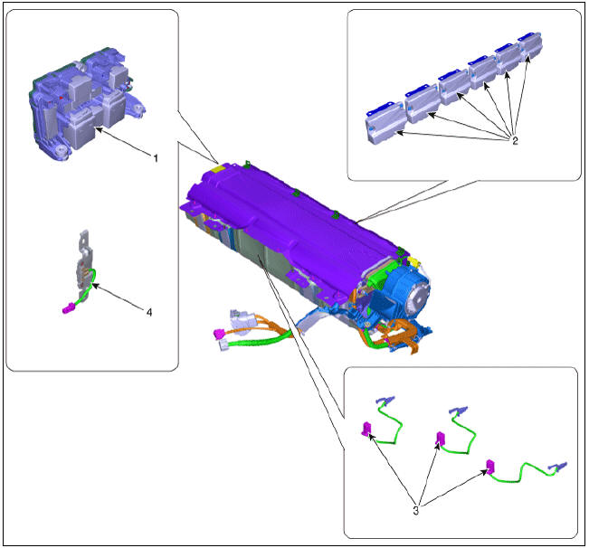
- Power Relay Assembly (PRA)
- Cell Monitoring Unit (CMU)
- Battery Temperature Sensor
- Runaway Arresting Device (RAD)
Warning
Main Relays (Positive, Negative), Pre-Charge Relay, Pre-Charge Resistor, and Battery Current Sensor are integrated into the PRA.
Sub High Voltage Battery
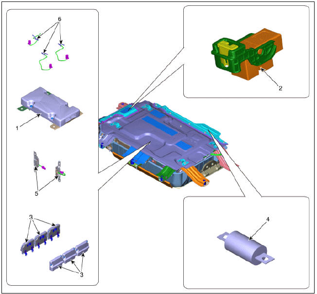
- BMS ECU
- Safety Plug
- Cell Monitoring Unit (CMU)
- Main Fuse
- Runaway Arresting Device (RAD)
- Battery Temperature Sensor
Warning
Main Relays (Positive, Negative), Pre-Charge Relay, Pre-Charge Resistor, and Battery Current Sensor are integrated into the PRA.
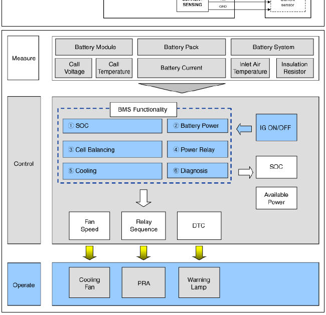
High Voltage Battery Control System / Schematic Diagrams
Schematic Diagram
Troubleshooting Flow

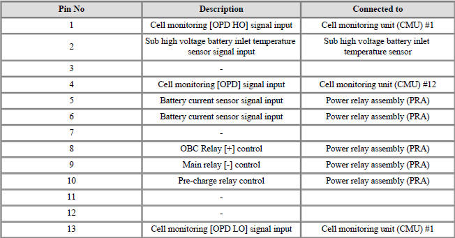
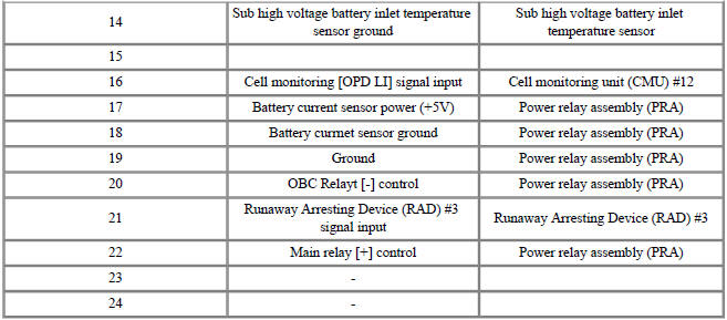
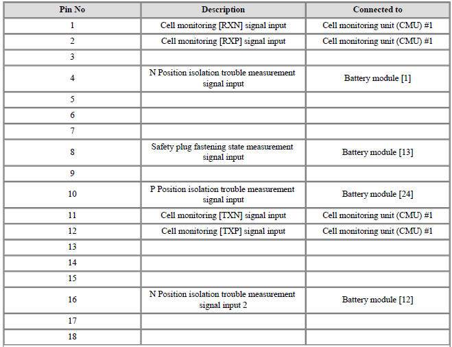
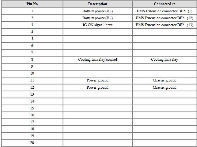
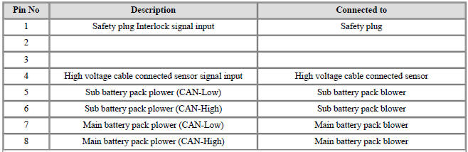
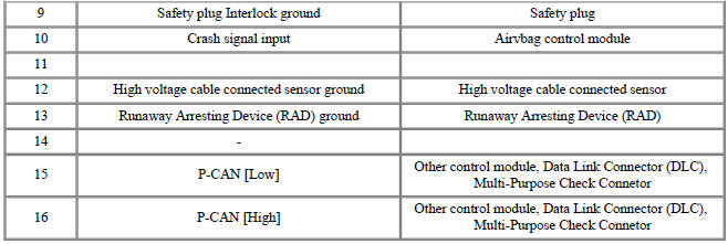
BMS ECU Terminal and Input/Output Signal
Terminal Funxtion
Connector (B11-1A)
Connector (B11-1B)

Connector (B11-2A)
Connector (B11-2B)
READ NEXT:
 Sub High Voltage Battery - Removal
Warning
Be sure to read and follow the "General Safety Information and
Caution" before doing any work related
with the high voltage system. Failure to follow the safety instructions may
result in serious electrical
injuries.
Safety Plug Description and operation
Description
Safety Plug is installed on the rear side of the high voltage battery and it
can mechanically shut the
high voltage circuit off when servicing the high voltage system. (i.e. High
Voltage Battery, Power
Relay Assembly, HPCU, BMS ECU
The Power Relay Assembly
Description
The Power Relay Assembly (PRA) consists of the positive and negative main
relays, pre-charge relay, pre-charge resistor and
battery current sensor. It is located inside the battery pack assembly and
controls the high voltage power c
SEE MORE:
Hybrid Control System / Components And Components Location
HPCU (Hybrid Power Control Unit)
On-Board Charger (OBC)
Charge Port
Power Cable (HPCU↔HSG,Electronic A/C
Compressor)
Power Cable (HPCU↔Main High Voltage Battery System)
Power Cable (Main High Voltage Battery System â
Automatic climate control system
Kia NIRO Hybrid
Type A
Type B
Driver's temperature control knob
Passenger's temperature control knob
AUTO (automatic control) button
OFF button
Fan speed control button
Mode selection button
Front windshield defroster bu
Categories
- Home
- KIA Niro EV, Hybrid - Second generation - (SG2) (2021-2024) - Owner's manual
- Kia Niro - First generation - (DE) (2017-2022) - Service and Repair Manual
- Contact Us