KIA Niro: The Power Relay Assembly
Description
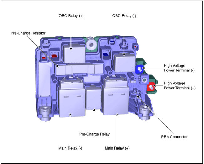
The Power Relay Assembly (PRA) consists of the positive and negative main relays, pre-charge relay, pre-charge resistor and battery current sensor. It is located inside the battery pack assembly and controls the high voltage power circuit between the high voltage battery and inverter by the control signal of BMS ECU.
PRA Operation Sequence
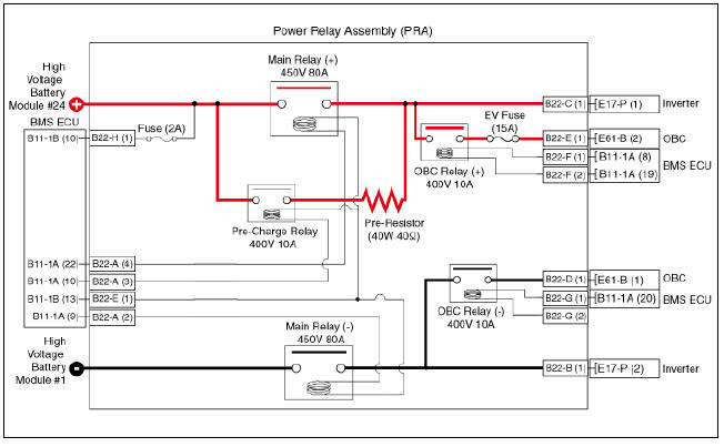
Circuit Diagram
Removal
Warning
- Be sure to read and follow the "General Safety Information and Caution" before doing any work related with the high voltage system. Failure to follow the safety instructions may result in serious electrical injuries.
- Be sure to read and follow the "High Voltage Shut-off Procedures" before doing any work related with the high voltage system. Failure to follow the safety instructions may result in serious electrical injuries
- Turn ignition switch OFF and disconnect the negative (-) battery cable.
- Shut off the high voltage circuit.
(Refer to Hybrid Control System - "High Voltage Shut-off Procedures")
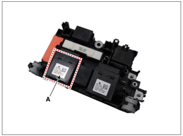
- Remove the power relay assembly.
(Refer to High Voltage Battery System - "Power Relay Assembly")
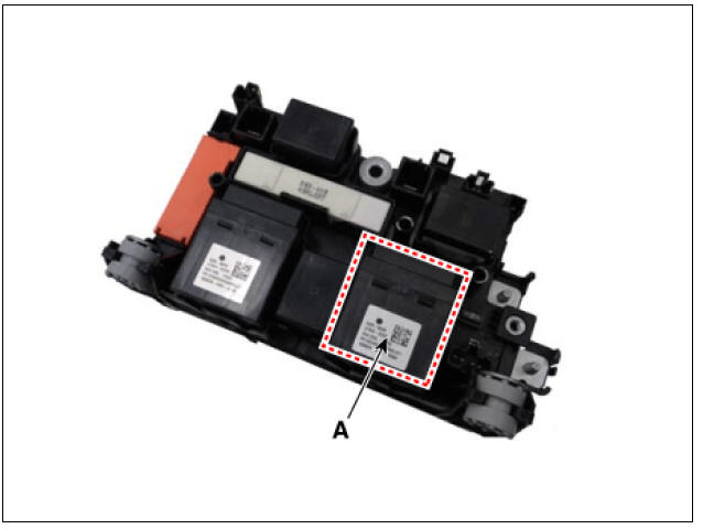
- Remove the main relay (A).
Main Relay (+)
Main Relay (-)
Installation
Warning
- Be sure to read and follow the "General Safety Information and Caution" before doing any work related with the high voltage system. Failure to follow the safety instructions may result in serious electrical injuries.
- Be sure to read and follow the "High Voltage Shut-off Procedures" before doing any work related with the high voltage system. Failure to follow the safety instructions may result in serious electrical injuries.
- Install the main relay in the reverse order of removal.
Inspection
Warning
- Be sure to read and follow the "General Safety Information and Caution" before doing any work related with the high voltage system. Failure to follow the safety instructions may result in serious electrical injuries.
- Be sure to read and follow the "High Voltage Shut-off Procedures" before doing any work related with the high voltage system. Failure to follow the safety instructions may result in serious electrical injuries.
Checking for Welding in the High Voltage Main Relay
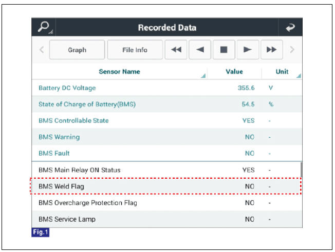
Using KDS service data to check for main relay weld damage
- Connect the KDS to the Data Link Connector (DLC).
- Turn the ignition switch ON.
- Check the BMS weld damage state in the KDS service data.
Using a Multimeter to measure weld damage
- Shut off the high voltage.
(Refer to "High Voltage Shut-off Procedures")
- Remove the high voltage battery rear cover.
(Refer to "High Voltage Battery System - "Case")
- Remove the inlet cooling duct.
(Refer to Hybrid Control System - "Cooling Duct")
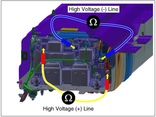
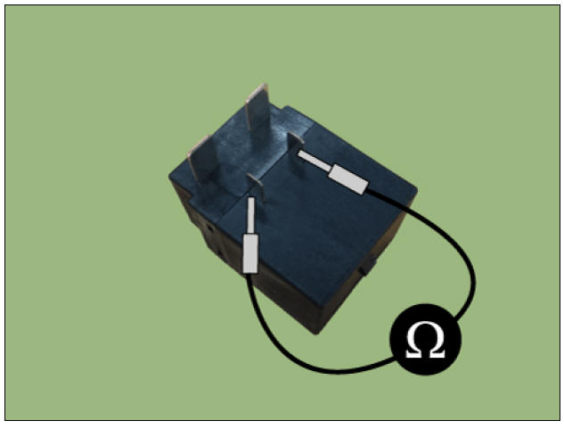
- Measure the high voltage main relay resistance and check for signs of weld damage.
Specification : ∞Ω (20ºC (68ºF))
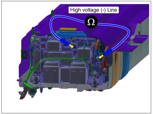
High voltage main relay (-) switch resistance
- Shut off the high voltage.
(Refer to "High Voltage Shut-off Procedures")
- Remove the high voltage battery rear cover.
(Refer to "High Voltage Battery System - "Case")
- Remove the inlet cooling duct.
(Refer to Hybrid Control System - "Cooling Duct")
- Measure the resistance between the high voltage power terminal (-) and the inverter power terminal (-).
Circuit inspection (Relay ON)
Warning
Inspect the high voltage main relay (-) activated by KDS.
- Connect the KDS to the Data Link Connector (DLC).
- Turn the ignition switch ON.
- Activate the main relay by using "Actuation Test" on the KDS as shown in the illustration below.
Warning
When the relay is ON, there is a relay operation sound.
High Voltage Main Relay Coil Resistance
- Shut off the high voltage.
(Refer to "High Voltage Shut-off Procedures")
- Remove the power relay assembly.
(High Battery System - "Power Relay Assembly")
- Check for continuity between the terminals using an ohmmeter.
READ NEXT:
 High Voltage Battery Cooling
Component
Location
Cooling Fan #1
Cooling Fan #2
Main High Voltage Battery Cooling Duct (Inlet)
Main High Voltage Battery Cooling Duct (Outlet)
Sub High Voltage Battery Cooling Duct (Inlet)
Sub High Voltage Battery Cooling Duct (Ou
Cooling Fan - Components and components location
Components
Cooling Fan #1
BLDC Motor
Main Connector
Cooling Fan #2
BLDC Motor
Main Connector
Removal
Warning
Be sure to read and follow the "General Safety Information and
Caution" before doing any work re
Cooling Fan Repair procedures
Installation
Warning
Be sure to read and follow the "General Safety Information and
Caution" before doing any work related with the high voltage system. Failure
to follow the safety
instructions may result in serious electrical
SEE MORE:
Navigation-based Smart Cruise Control operation
Operating conditions
Navigation-based Smart Cruise Control
is ready to operate if all of the following
conditions are satisfied:
Smart Cruise Control is operating
Driving on main roads of highways (or
motorways)
NOTICE
For more details
Engine Coolant Temperature Sensor (ECTS)
Specification
Description
Located in the engine coolant passage of the cylinder head, Engine Coolant
Temperature Sensor
(ECTS) detects the engine coolant temperature. The ECTS uses a thermistor with
resistance in
proportion to the tempera
Categories
- Home
- KIA Niro EV, Hybrid - Second generation - (SG2) (2021-2024) - Owner's manual
- Kia Niro - First generation - (DE) (2017-2022) - Service and Repair Manual
- Contact Us