KIA Niro: High Voltage Battery Cooling
Kia Niro - First generation - (DE) (2017-2022) - Service and Repair Manual / Service Highlight / High Voltage Battery Cooling
Component
Location
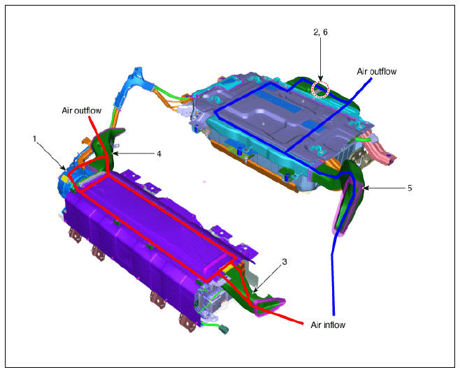
- Cooling Fan #1
- Cooling Fan #2
- Main High Voltage Battery Cooling Duct (Inlet)
- Main High Voltage Battery Cooling Duct (Outlet)
- Sub High Voltage Battery Cooling Duct (Inlet)
- Sub High Voltage Battery Cooling Duct (Outlet)
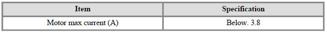
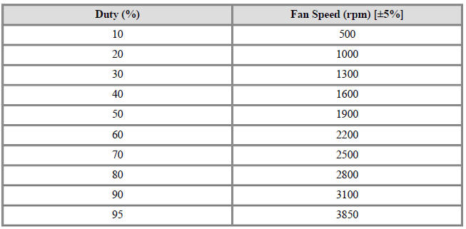
Specification
Current
Duty
Description
The cooling Fan consists of the main connector, the cooling fan relay and the
BLDC motor. It is
controlled by the BMS ECU PWM signal which varies with the high voltage battery
condition (9-
Speed).
READ NEXT:
 Cooling Fan - Components and components location
Components
Cooling Fan #1
BLDC Motor
Main Connector
Cooling Fan #2
BLDC Motor
Main Connector
Removal
Warning
Be sure to read and follow the "General Safety Information and
Caution" before doing any work re
Cooling Fan Repair procedures
Installation
Warning
Be sure to read and follow the "General Safety Information and
Caution" before doing any work related with the high voltage system. Failure
to follow the safety
instructions may result in serious electrical
Сharge port
Description
Location of normal charge port in the front fender of vehicle. The charge
starts when the ICCB or the
is connected to charge port.
Removal
Warning
Be sure to read and follow the "General Safety Information and
Ca
SEE MORE:
Auto Lighting Control System
Specifications
Auto Lighting Control System / Components And Components Location
Auto light sensor
Headlamps
Lighting switch (Auto)
Rear combination lamps
BCM (Body Control Module)
Description
It's a system that uses i
Coat hook
A coat hook is next to the left rear grab
handle.
WARNING
Do not hang other objects such as hangers
or hard objects except clothes. Also,
do not put heavy, sharp or breakable
objects in the clothing's pockets. In an
accident or when the cu
Categories
- Home
- KIA Niro EV, Hybrid - Second generation - (SG2) (2021-2024) - Owner's manual
- Kia Niro - First generation - (DE) (2017-2022) - Service and Repair Manual
- Contact Us