KIA Niro: Cooling Fan - Components and components location
Kia Niro - First generation - (DE) (2017-2022) - Service and Repair Manual / Service Highlight / High Voltage Battery Cooling / Cooling Fan - Components and components location
Components
Cooling Fan #1
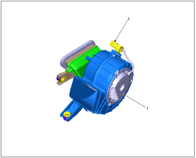
- BLDC Motor
- Main Connector
Cooling Fan #2
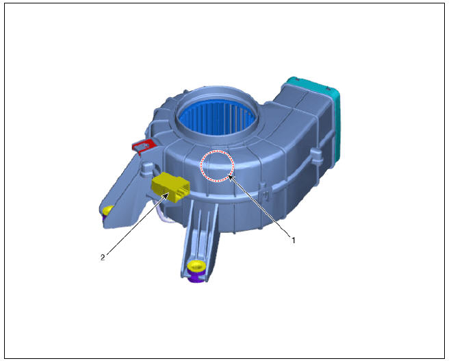
- BLDC Motor
- Main Connector
Removal
Warning
- Be sure to read and follow the "General Safety Information and
Caution" before doing any work related with the high voltage system. Failure
to follow the safety
instructions may result in serious electrical injuries. - Be sure to read and follow the "High Voltage Shut-off Procedures" before doing any work related with the high voltage system. Failure to follow the safety instructions may result in serious electrical injuries.
Cooling Fan #1 (High Voltage Main Battery)
- Shut off the high voltage circuit.
(Refer to Hybrid Control System - "High Voltage Shut-off Procedures")
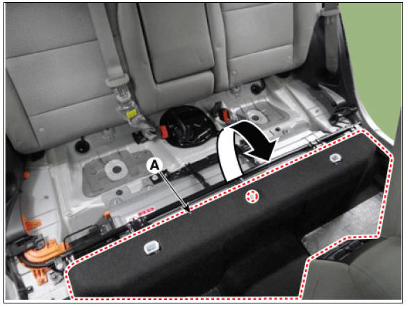
- Remove the rear seat cushion.
(Refer to Body - "Rear Seat Assembly")
- Remove the rear door scuff trim.
(Refer to Body - "Door Scuff Trim")
- Remove the inlet cooling duct.
(Refer to High Voltage Battery Cooling System - "Cooling Duct")
- Open the high voltage battery cushion (A) in the direction of an arrow.
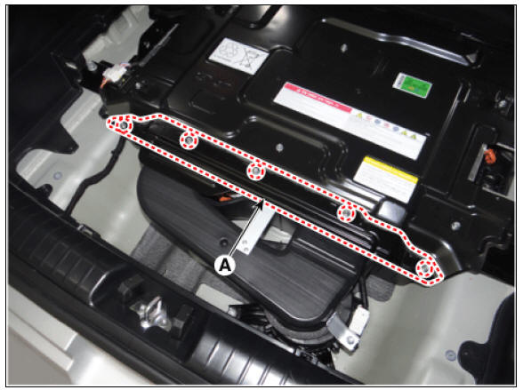
- Remove the upper frame (A) after loosening the mounting bolts and nuts.
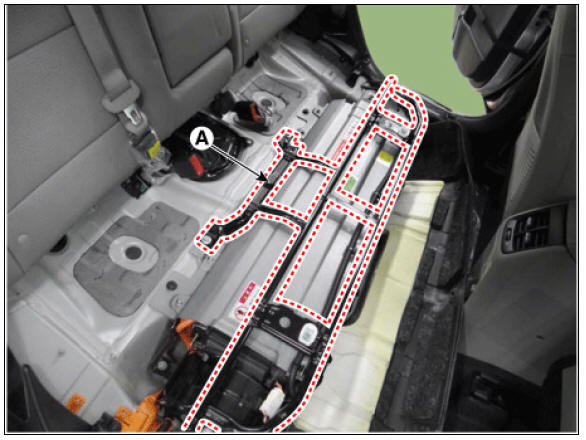
- Remove the outlet cooling duct.
(Remove the High Voltage Cooling System - "Cooling Duct")
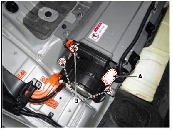
- Disconnect the cooling fan connector (A).
- Remove the cooling fan after loosening the mounting bolts and nuts (B).
Cooling Fan #2 (High Voltage Sub Battery)
- Switch "OFF" the ignition and disconnect the negative (-) terminal of the auxiliary 12V battery.
- Shut off the high voltage circuit.
(Refer to Hybrid Control System - "High Voltage Shutoff Procedure")
- Remove the high voltage rear cover (A) after loosening the mounting bolt.
High Voltage Battery Rear Cover mounting bolt : 7.8 - 11.8 N*m (0.8 - 1.2 kgf*m, 5.8 - 8.7 lb*ft)
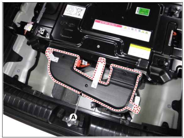
- Remove the rear outlet cooling duct (A) after loosening the mounting bolt.
Rear Outlet Cooling Duct mounting bolt : 7.8 - 11.8 N*m (0.8 - 1.2 kgf*m, 5.8 - 8.7 lb*ft)
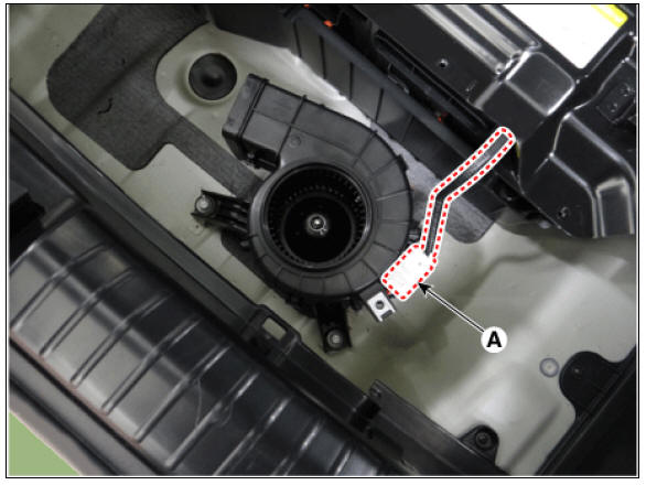
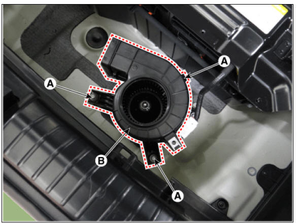
- Remove the cooling fan connector (A).
- Remove the cooling fan (B) after loosening the mounting bolts (A).
READ NEXT:
 Cooling Fan Repair procedures
Installation
Warning
Be sure to read and follow the "General Safety Information and
Caution" before doing any work related with the high voltage system. Failure
to follow the safety
instructions may result in serious electrical
Сharge port
Description
Location of normal charge port in the front fender of vehicle. The charge
starts when the ICCB or the
is connected to charge port.
Removal
Warning
Be sure to read and follow the "General Safety Information and
Ca
Low Voltage DC/DC Converter (LDC)
Component Location
Low Voltage DC/DC Converter (LDC) (HPCU)
Low Voltage DC/DC Converter (LDC) power output
terminal (+) (DC 12V)
Low Voltage DC/DC Converter (LDC) ground terminal (-)
Schematic Diagram
Low Voltage DC/DC Converter
SEE MORE:
In-car Sensor
In-car Sensor Description and operation
Description
The in-car air temperature sensor is built into the heater & A/C control
unit.
The sensor consists of a thermistor that measures the temperature inside the
vehicle. The signal
decided
Good driving practices
Never change the gear from P (Park)
or N (Neutral) to any other position
with the accelerator pedal depressed.
Never change the gear into P (Park)
when the vehicle is moving.
Stop the vehicle completely before
changing the gear into R
Categories
- Home
- KIA Niro EV, Hybrid - Second generation - (SG2) (2021-2024) - Owner's manual
- Kia Niro - First generation - (DE) (2017-2022) - Service and Repair Manual
- Contact Us