KIA Niro: Low Voltage DC/DC Converter (LDC)
Component Location
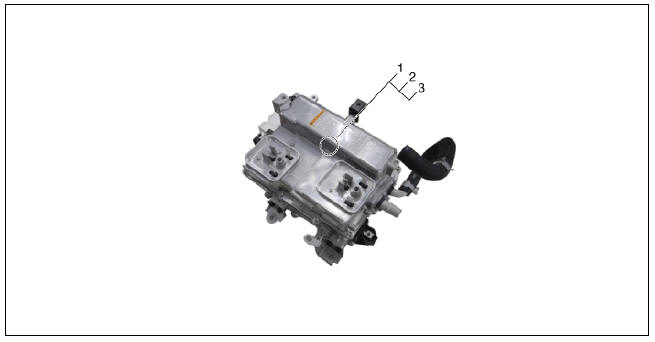
- Low Voltage DC/DC Converter (LDC) (HPCU)
- Low Voltage DC/DC Converter (LDC) power output terminal (+) (DC 12V)
- Low Voltage DC/DC Converter (LDC) ground terminal (-)
Schematic Diagram
Low Voltage DC/DC Converter (LDC) / Repair Procedures
Removal
Warning
- Be sure to read and follow the "General Safety Information and Caution" before doing any work related with the high voltage system. Failure to follow the safety instructions may result in serious electrical injuries.
- Be sure to read and follow the "High Voltage Shut-off
Procedures" before doing any work related with the high voltage system.
Failure to follow the safety instructions may result in serious electrical injuries.
- Shut off the high voltage.
(Refer to "High voltage Shut-off Procedures")
- Remove the air cleaner assembly and air duct.
(Refer to Engine Mechanical System - "Air Cleaner")
- Remove the ECM & TCM bracket assembly.
(Refer to Engine Control/Fuel System - "Engine Control Module")
- Drain the coolant of hybrid motor cooling system.
(Refer to Hybrid Motor Cooling System - "Coolant")
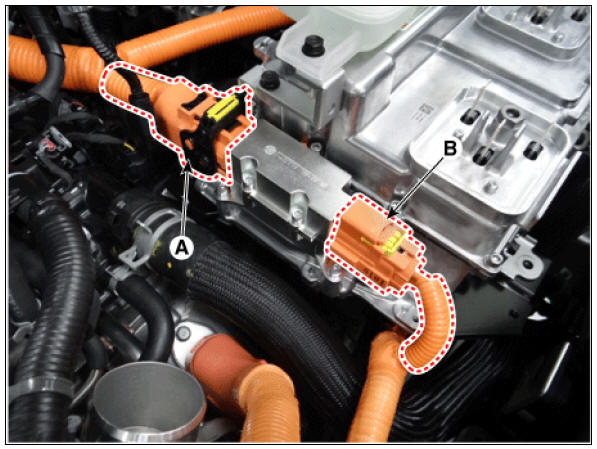
- Disconnect the motor power cable connector (A) and HSG power cable connector (B) after loosening the mounting bolts.
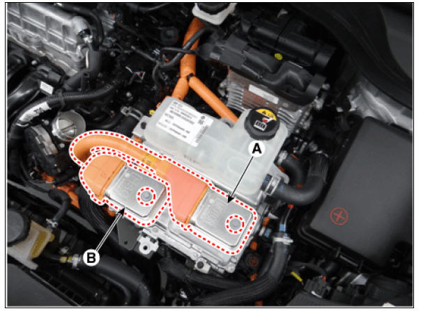
- Disconnect the power cable (A) and inverter power cable (B) from the HPCU.
Warning
Remove the inverter power cale in the follwing order.
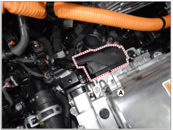
- Disconnect the HCU & inverter (MCU) connector (A).
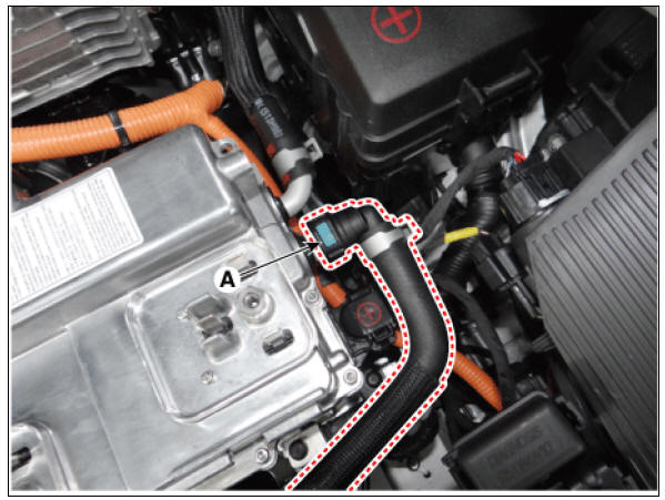
- Disconnect the coolant outlet hose & pipe after loosening the mounting bolt (A).
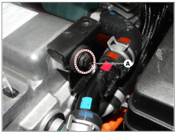
- Disconnect the coolant inlet hose quick-connector (A).
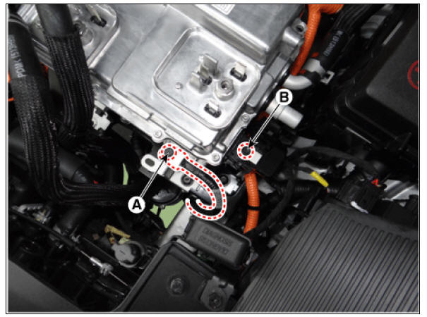
- Remove the LDC power outlet cable mounting bolt (A) and ground cable bolt (B).
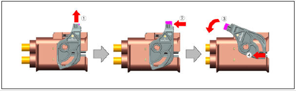
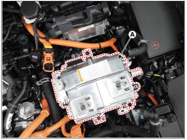
- Remove the HPCU (A) after loosening the mounting bolts.
Installation
Warning
- Be sure to read and follow the "General Safety Information and Caution" before doing any work related with the high voltage system. Failure to follow the safety instructions may result in serious electrical injuries.
- Be sure to read and follow the "High Voltage Shut-off
Procedures" before doing any work related with the high voltage system.
Failure to follow the safety instructions may result in serious electrical injuries.
- Install the LDC in the reverse order of removal.
- Refill the hybrid motor cooling system coolant and perform air bleeding
by using the KDS.
(Refer to Hybrid Motor Cooling System - "Coolant")
Warning
Perform HCU Variant Coding and Engine Clutch / Motor Resolver learning after replacing the HPCU.
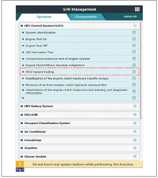
HCU Variant Coding
- Turn the ignition switch OFF.
- Connect the KDS to Data Link Connector (DLC).
Turn the ignition switch ON.
- Select "Vehicle, Model year, Engine, System".
- Select "Vehicle S/W Management".
- Select "HCU Variant Coding".
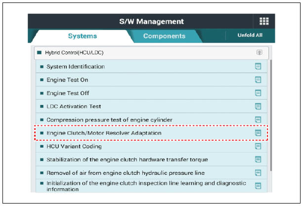
Engine clutch/motor resolver adaptation
- Turn the ignition switch OFF.
- Connect the KDS to Data Link Connector (DLC).
Turn the ignition switch ON.
- Select "Vehicle, Model year, Engine, System".
- Select "Vehicle S/W Management".
- Select "Engine clutch/motor resolver adaptation.".
READ NEXT:
 Hybrid Drive Motor Assembly Repair procedures
Description
The hybrid motor system is equipped with two electric motors - HSG and
drive motor.
The traction motor operates to move the vehicle, to reduce Noise,
Vibration, and Harshness (NVH) while driving and to
improve fuel efficienc
Hybrid Starter Generator(HSG) Repair procedures
Hybrid Starter Generator(HSG) Components and components location
Components
Hybrid starter generator (HSG)
HSG bracket
Specification
Hybrid Starter Generator(HSG) Repair procedures
Inspection
Inspect the line to line resistanc
SEE MORE:
Air Bleeding Tool Removal Procedure
Close the air shut-off valve (A) first, after disconnecting the air hose
(B), bleed air in the reservoir tank by opening the air shut-off valve
(A) slowly.
Warning
To prevent backflow of brake fluid, be sure to open the air shut-off
Water Temperature Control Assembly
Removal and Installation
Water Temperature Control Assembly
Disconnect the battery negative terminal.
Loosen the drain plug, and drain the engine coolant. Remove the
reservoir cap to help drain the coolant
faster.
(Refer to Cool
Categories
- Home
- KIA Niro EV, Hybrid - Second generation - (SG2) (2021-2024) - Owner's manual
- Kia Niro - First generation - (DE) (2017-2022) - Service and Repair Manual
- Contact Us