KIA Niro: Safety Plug Description and operation
Kia Niro - First generation - (DE) (2017-2022) - Service and Repair Manual / Service Highlight / Power Relay Assembly (PRA) / Safety Plug Description and operation
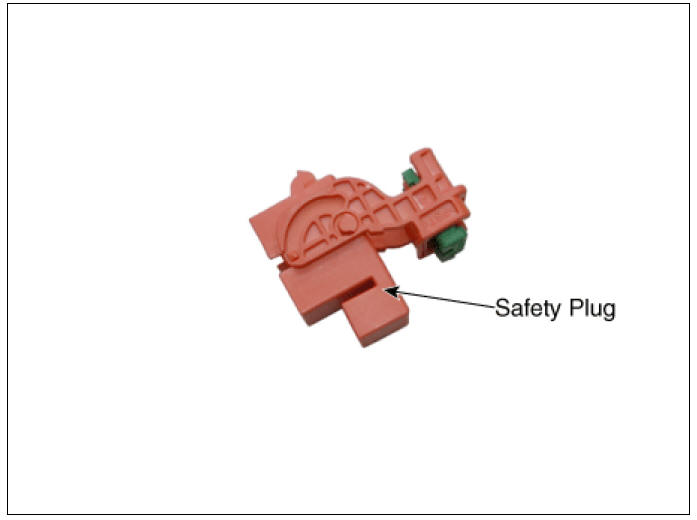
Description
Safety Plug is installed on the rear side of the high voltage battery and it
can mechanically shut the
high voltage circuit off when servicing the high voltage system. (i.e. High
Voltage Battery, Power
Relay Assembly, HPCU, BMS ECU, Hybrid Drive Motor, Inverter, HSG, LDC, Power
Cable, etc.)
It includes a fuse in order to prevent the high voltage system from overcurrent.
Circuit Diagram
Harness Connector (Interlock)
Safety Plug Repair procedures
Removal
Warning
- Be sure to read and follow the "General Safety Information and Caution" before doing any work related with the high voltage system. Failure to follow the safety instructions may result in serious electrical injuries.
- Be sure to read and follow the "High Voltage Shut-off Procedures" before doing any work related with the high voltage system. Failure to follow the safety instructions may result in serious electrical injuries.
- Turn the ignition switch OFF.
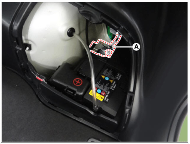
- Remove the auxiliary 12V battery cover (A).
- Disconnect the auxiliary 12V battery negative (-) terminal.
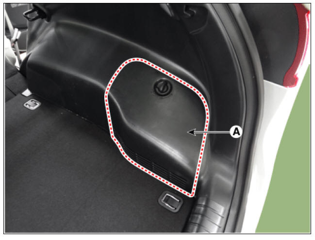
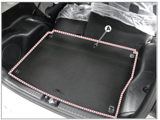
- Remove the luggage board (A).
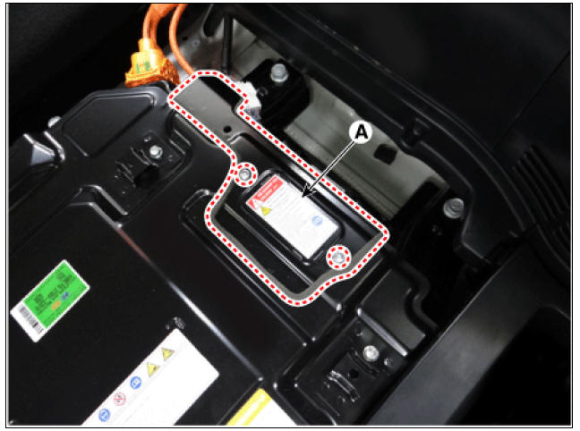
- Remove the safety plug cover (A) after loosening the mounting bolts.
Installation
Warning
- Be sure to read and follow the "General Safety Information and Caution" before doing any work related with the high voltage system. Failure to follow the safety instructions may result in serious electrical injuries.
- Be sure to read and follow the "High Voltage Shut-off Procedures" before doing any work related with the high voltage system. Failure to follow the safety instructions may result in serious electrical injuries.
- Install the Safety Plug in the reverse order of removal.
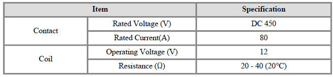
Specification
READ NEXT:
 The Power Relay Assembly
Description
The Power Relay Assembly (PRA) consists of the positive and negative main
relays, pre-charge relay, pre-charge resistor and
battery current sensor. It is located inside the battery pack assembly and
controls the high voltage power c
High Voltage Battery Cooling
Component
Location
Cooling Fan #1
Cooling Fan #2
Main High Voltage Battery Cooling Duct (Inlet)
Main High Voltage Battery Cooling Duct (Outlet)
Sub High Voltage Battery Cooling Duct (Inlet)
Sub High Voltage Battery Cooling Duct (Ou
Cooling Fan - Components and components location
Components
Cooling Fan #1
BLDC Motor
Main Connector
Cooling Fan #2
BLDC Motor
Main Connector
Removal
Warning
Be sure to read and follow the "General Safety Information and
Caution" before doing any work re
SEE MORE:
In the event of brake failure (Kia NIRO Hybrid)
Operation
Make an emergency stop with the
parking brake.
Operating condition(s)
The brake has failed
WARNING
Avoid applying the parking brake to stop
the vehicle while it is moving except in
an emergency situation. Applying the
pa
Low Voltage DC/DC Converter (LDC)
Component Location
Low Voltage DC/DC Converter (LDC) (HPCU)
Low Voltage DC/DC Converter (LDC) power output
terminal (+) (DC 12V)
Low Voltage DC/DC Converter (LDC) ground terminal (-)
Schematic Diagram
Low Voltage DC/DC Converter
Categories
- Home
- KIA Niro EV, Hybrid - Second generation - (SG2) (2021-2024) - Owner's manual
- Kia Niro - First generation - (DE) (2017-2022) - Service and Repair Manual
- Contact Us