KIA Niro: Front View Camera Unit
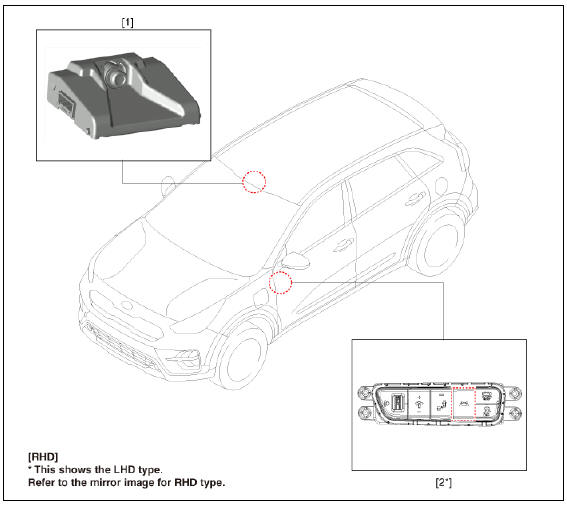
- Front view camera unit
- LKA ON/OFF switch
Description
System Function
- Lane Keeping Assist (LKA) : The function detects unintentional lane departure and assists to keep the lane by using alarms and MDPS steering control.
- High Beam Assist (HBA) : The function detects head lamp and tail lamp lights of vehicle ahead and turns the high beam ON/ OFF.
- Driver Attention Warning (DAW) : The function express alert and warning message through analysis driving pattern.
- Lane Following Assist (LFA) : This function work together with SCC operating and lane following control function.
System Description
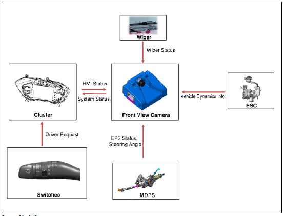
Lane Keeping Assist (LKA)
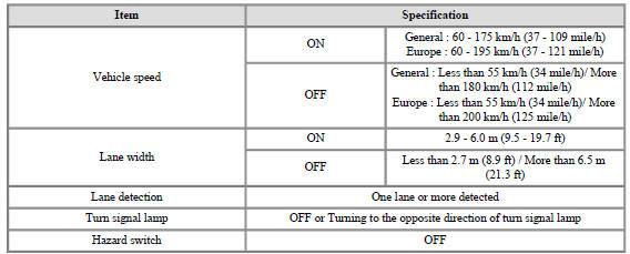
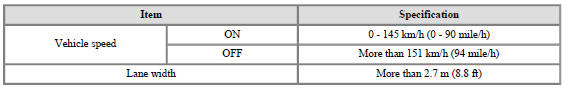
- Operation specification
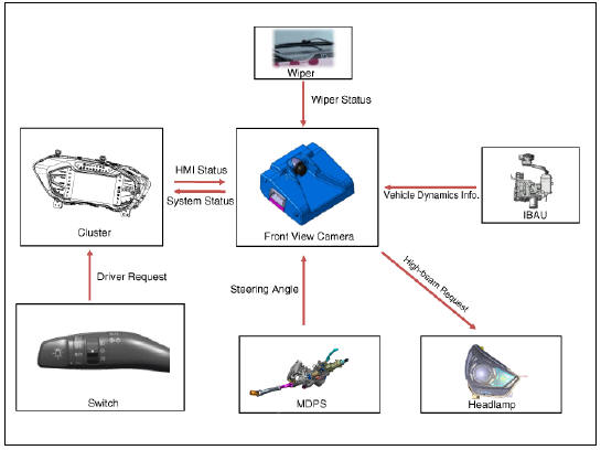
- System components
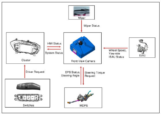
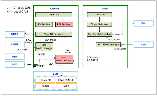
- System block diagram
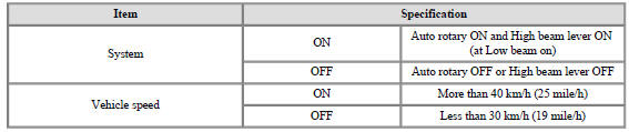
High Beam Assist (HBA)
- Operation specification
- System components
- System block diagram
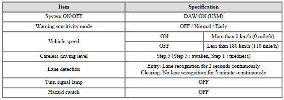
Driver Attention Warning (DAW)
- Operation specification
- System components
- System block diagram
Lane Following Assist (LFA)
- Operation specification
- System components
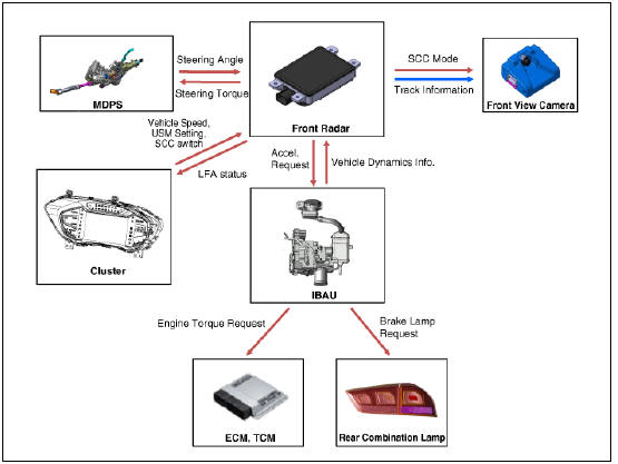
- System block diagram
Limitation of the System
This system monitors the driving situations through the radar and the camera. Thus, for a situation out of the sensing range, the system may not normally operate.
The System may be limited when :
- The radar sensor or camera is blocked with a foreign object or debris.
- The camera lens is contaminated due to tinted filmed or coated windshield, damaged glass, or stuck of foreign matter (sticker, bug, etc.) on the glass.
- Inclement weather such as heavy rain or snow obscures the field of view of the radar sensor or camera.
- The target in front is too small to be detected
- The vehicle in front is an oversize vehicle or trailer that is too big to be detected by the camera recognition system (for example a tractor trailer, etc.).
- The camera's field of view is not well illuminated (either too dark or too much reflection or too much backlight that obscures the field of view)
- The vehicle in front does not have their rear lights ON or their rear lights are located in an unsual location (modified).
- The windshield glass is fogged up and the clear view of the road has been obstructed.
- The camera or radar is damaged.
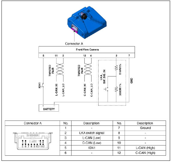
Circuit Diagram
READ NEXT:
 Front View Camera Unit - Removal
Inspection
In the body electrical system, failure can be quickly diagnosed by using
the vehicle diagnostic system (KDS).
The diagnostic system (KDS) provides the following information.
(1) Self diagnosis : Checking failure and code number
Service Point Target Auto Calibration (SPTAC) Procedure
Install the SST (09964-C1200) on the roof center above the vehicle's
front windshield.
Have the laser illuminate starting from the roof center and to passing
through the emblem center.
Warning
The level laser must be se
SEE MORE:
High Beam Assist (HBA)
High Beam Assist (HBA) (if equipped) (Kia NIRO Hybrid)
High Beam Assist is a function that automatically
adjusts the headlamp range
(switches between high beam and low
beam) depending on the brightness of
detected vehicles and certain road c
Interior overview
Left-hand drive (Kia NIRO Hybrid)
Right-hand drive (Kia NIRO Hybrid)
Inside door handle
Seat position memory system
Outside rearview mirror folding switch
Outside rearview mirror control switch
Central door lock/unlock switch
Categories
- Home
- KIA Niro EV, Hybrid - Second generation - (SG2) (2021-2024) - Owner's manual
- Kia Niro - First generation - (DE) (2017-2022) - Service and Repair Manual
- Contact Us