KIA Niro: Heater & A/C Control Unit
Kia Niro - First generation - (DE) (2017-2022) - Service and Repair Manual / Heating, Ventilation and Air Conditioning / Heater & A/C Control Unit
Heater & A/C Control Unit / Components And Components Location
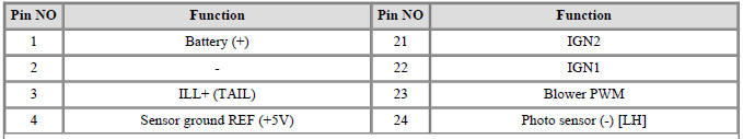
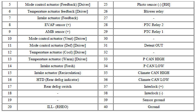
Connector A
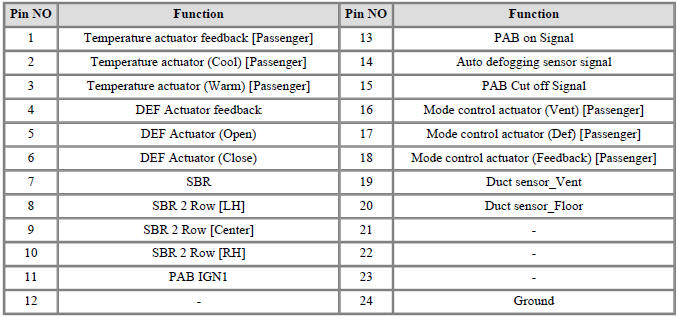
Connector B
Heater & A/C Control Unit / Repair Procedures
Self Diagnosis
- Self-diagnosis process.
Warning
When operating the self-diagnostics, the below fault (self-diagnostics code) will blink at 0.5 seconds interval on the temperature display settings (driver's side only) and the remaining symbols are OFF .
- Fault code display
(1) Continuance operation : DTC code.
(2) Continuance operation : DTC code.
(3) STEP operation.
- Same with continuance operation for normal or one fault code
- DTC code
Replacement
- Disconnect the negative (-) battery terminal.
- Remove the cluster fascia panel.
(Refer to Body - "Cluster Fascia Panel")
- Remove the crash pad garnish (RH).
(Refer to Body - "Crash Pad Garnish")
- Remove the audio and AVN Keyboard.
(Refer to Body Electrical System - "Audio/AVN Keyboard")
- Remove the center fascia lower panel (A).
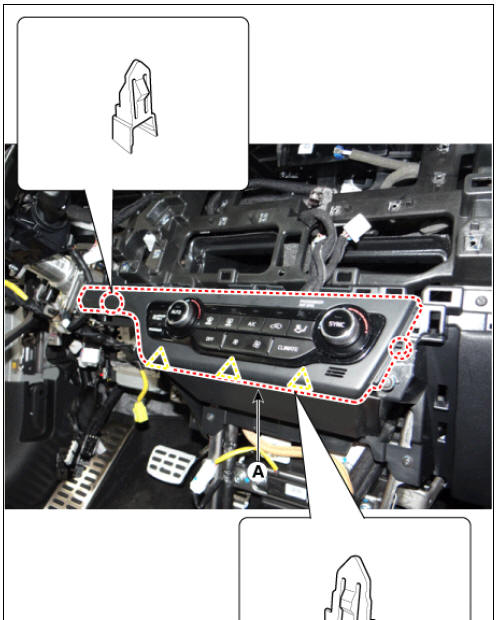
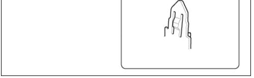
- Loosen the screw and remove the heater and air conditioner control unit (A).
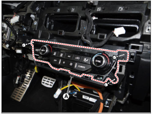
- Remove the heater and the air conditioning control unit connector (A).
- Install in the reverse order of removal.
READ NEXT:
 Heater
Heater Unit Components and components location
Heater unit assembly
Components
LH
Heater Core Cover
Heater Core Assembly
PTC Heater
Duct Sensor
Shower Duct (LH)
Evaporator lower case insulation
Heater Lower Case
Drain
Heater Unit Repair procedures
Replacement
Warning
When prying with a flat-tip screwdriver or a prying trim tool, wrap
a protective tape around the related parts and the tool to
prevent damage.
Disconnect the negative (-) battery terminal.
Recover the refrigerant with a
Heater Core Repair procedures | Positive Temperature Coefficient (The PTC)
Replacement
Disconnect the negative (-) battery terminal.
Remove the heater and blower assembly.
(Refer to Heater -"Heater Unit")
Loosen the mounting screws and remove heater core cover (A).
Pull out t
SEE MORE:
Immobilizer system
The immobilizer system reduces the risk
of unauthorized vehicle use.
It is comprised of a small transponder in
the ignition switch and electronic
devices inside the vehicle. It checks and
determines and verifies if the ignition
key is valid o
Refrigerant System Service Basics (R- 1234yf)
Refrigerant Identification
Do not mix HFO-1234yf (R-1234yf) in the vehicle with other refrigerant,
such as R-12, R-134a and etc.
Use only the UL-listed service equipment certified to meet the
requirements of SAE standards to recover and r
Categories
- Home
- KIA Niro EV, Hybrid - Second generation - (SG2) (2021-2024) - Owner's manual
- Kia Niro - First generation - (DE) (2017-2022) - Service and Repair Manual
- Contact Us