KIA Niro: Heater
Heater Unit Components and components location
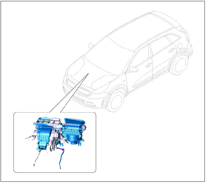
- Heater unit assembly
Components
LH
- Heater Core Cover
- Heater Core Assembly
- PTC Heater
- Duct Sensor
- Shower Duct (LH)
- Evaporator lower case insulation
- Heater Lower Case
- Drain hose
- Mode Control Actuator (LH)
- Temperature Control Actuator (LH)
- Duct Sensor (VENT)
- Heater Case (LH)
RH
- Anti Noise Pad
- Seal
- Vent Door Assembly
- Blower door assembly
- Vent door assembly (console)
- Console Cover
- Temperature Control Door Assembly
- Separator
- Heater Case (RH)
- Auto Defogging Door Assembly
- Anti Noise Pad
- Evaporator hose seal
- Evaporator Core Assembly
- Auto Defogging Actuator
- Mode Control Actuator (RH)
- Temperature Control Actuator (RH)
- Evaporator Temperature Sensor
- Shower Duct (RH)
- Heater Unit Repair procedures
- Heater Core Repair procedures | Positive Temperature Coefficient (The PTC)
- Temperature Control Actuator
- Mode Control Actuator Repair procedures
- Auto Defogging Actuator
READ NEXT:
 Heater Unit Repair procedures
Replacement
Warning
When prying with a flat-tip screwdriver or a prying trim tool, wrap
a protective tape around the related parts and the tool to
prevent damage.
Disconnect the negative (-) battery terminal.
Recover the refrigerant with a
Heater Core Repair procedures | Positive Temperature Coefficient (The PTC)
Replacement
Disconnect the negative (-) battery terminal.
Remove the heater and blower assembly.
(Refer to Heater -"Heater Unit")
Loosen the mounting screws and remove heater core cover (A).
Pull out t
SEE MORE:
Restraint - General information
General
The supplemental restraint system (SRS) is designed to supplement the seat
belt to help reduce the risk
or severity of injury to the driver and passenger by activating and deploying
the driver, passenger, side
airbag and belt pretensio
Memory Power Seat Switch
Connector and Terminal Function
Memory power seat switch Repair procedures
Removal
Disconnect the negative (-) battery terminal.
Remove the driver front door trim.
(Refer to Body - "Front Door Trim")
Remove the memory power
Categories
- Home
- KIA Niro EV, Hybrid - Second generation - (SG2) (2021-2024) - Owner's manual
- Kia Niro - First generation - (DE) (2017-2022) - Service and Repair Manual
- Contact Us