KIA Niro: Temperature Control Actuator
Temperature Control Actuator Components and components location
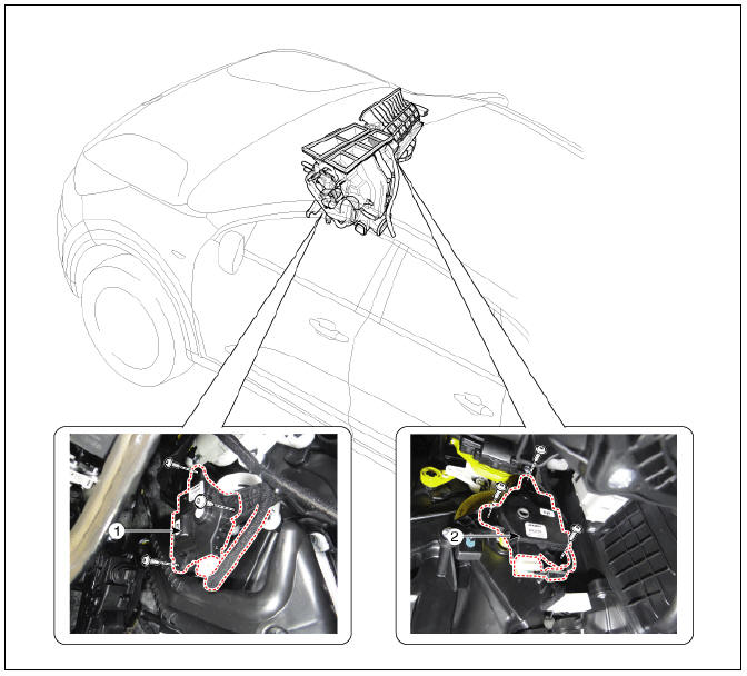
- Temperature control actuator (LH)
- Temperature control actuator (RH)
Description
Located in the heater unit, the temperature control actuator regulates the temperature in the following procedure.
The signal from the control unit adjusts the position of the temperature door by operating the temperature switch. Then the temperature will be regulated by the hot/cold air ratio decided by the position of the temperature door.
Temperature Control Actuator Repair procedures
Inspection
- Switch "OFF" the ignition.
- Disconnect the temperature control actuator connector.
- Verify that the temperature control actuator operates to the cool position when connecting 12V to terminal 3 and grounding terminal 7.
Verify that the temperature control actuator operates to the warm position when connected in reverse.
Temperature control actuator (LH)
- -
- -
- Cool position
- Sensor (+ 5V)
- Feedback signal
- Sensor ground
- Warm position
Temperature control actuator (RH)
- -
- -
- Cool position
- Sensor (+ 5V)
- Feedback signal
- Sensor ground
- Warm position
- Connect the temperature control actuator connector.
- Switch "ON" the ignition.
- Check the voltage between terminals 5 and 6.
Specification
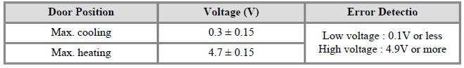
It will feedback the current position of the actuator to controls.
- If the measured voltage is not within specification, substitute with a known-good temperature control actuator and check for proper operation.
- Replace the temperature control actuator if it is proved that there is a problem with it.
Replacement
Driver side
- Disconnect the negative (-) battery terminal.
- Remove the crash pad lower panel.
(Refer to Body - "Crash Pad Lower Panel")
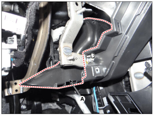
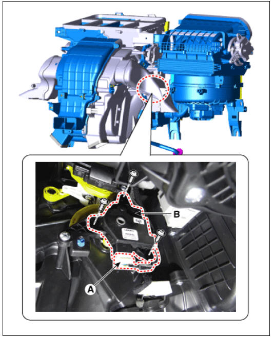
- Loosen the mounting screw and remove the cockpit shower duct (A).
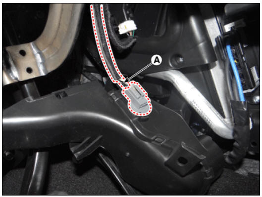
- Disconnect the duct sensor connector (A).
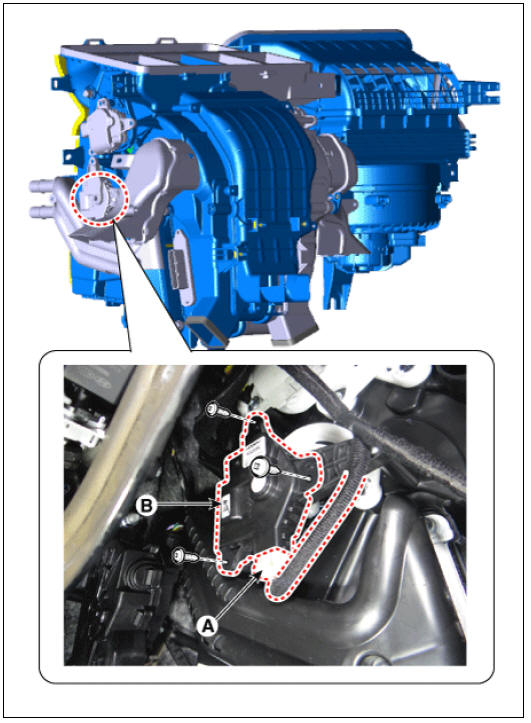
- Disconnect the connector (A) and then remove the temperature control actuator (B) after loosening the mounting screws.
- Install in the reverse order of removal.
Passenger side
- Disconnect the negative (-) battery terminal.
- Remove the glove box housing.
(Refer to Body - "Glove Box Housing")
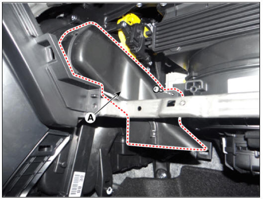
- Remove the passenger side shower duct (A) after loosening the screw.
- Disconnect the connector (A) and then remove the temperature control actuator (B) after loosening the mounting screws.
- Install in the reverse order of removal.
READ NEXT:
 Mode Control Actuator Repair procedures
Mode Control Actuator Components and components location
Mode control actuator (LH)
Mode control actuator (RH)
Description
Located in the heater unit, the mode control actuator adjusts the position of
the mode door by
operating the m
Auto Defogging Actuator
Description
Installed on the windshield glass, the auto defogging sensor detects humidity
to blow out wind for
defogging to improve visibility and driver comfort. The air conditioner control
module receives a
signal from the sensor and restrai
SEE MORE:
How to disconnect charging connector in emergency
Before disconnecting the charging
connector, make sure the doors are
unlocked. When the door is locked,
the charging connector lock system
will not allow disconnection. To prevent
charging cable theft, the
charging connector cannot be
Cylinder Block Repair procedures
Warning
Be sure to read and follow the "General Safety Information and
Caution" before doing any work related
with the high voltage system. Failure to follow the safety instructions may
result in serious electrical
injuries.
Be sure t
Categories
- Home
- KIA Niro EV, Hybrid - Second generation - (SG2) (2021-2024) - Owner's manual
- Kia Niro - First generation - (DE) (2017-2022) - Service and Repair Manual
- Contact Us