KIA Niro: Mode Control Actuator Repair procedures
Mode Control Actuator Components and components location
- Mode control actuator (LH)
- Mode control actuator (RH)
Description
Located in the heater unit, the mode control actuator adjusts the position of the mode door by operating the mode control actuator based on the signal of the A/C control unit. Pressing the mode select switch makes the mode control actuator shift in order of Vent → Bi-Level → Floor → Mix.
Mode Control Actuator Repair procedures
Inspection
- Switch "OFF" the ignition.
- Disconnect the mode control actuator connector.
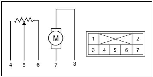
- Verify that the mode control actuator operates to the defrost mode when connecting 12V to terminal 3 and grounding terminal 7.
Verify that the mode control actuator operates to the vent mode when connected in reverse.
Mode control actuator (LH)
- -
- -
- Vent mode
- Sensor ground
- Feedback signal
- Sensor (+ 5V)
- Defrost mode
Mode control actuator (RH)

- -
- -
- Vent mode
- Sensor ground
- Feedback signal
- Sensor (+ 5V)
- Defrost mode
- Connect the mode control actuator connector.
- Switch "ON" the ignition.
- Check the voltage between terminals 4 and 5.
Specification
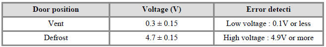
It will feedback the current position of the actuator to controls.
- If the measured voltage is not within specification, substitute with a known-good mode control actuator and check for proper operation.
- Replace the mode control actuator if it is proved that there is a problem with it.
Replacement
Driver side
- Disconnect the negative (-) battery terminal.
- Remove the main crash pad assembly.
(Refer to Body - "Main Crash Pad Assembly".)
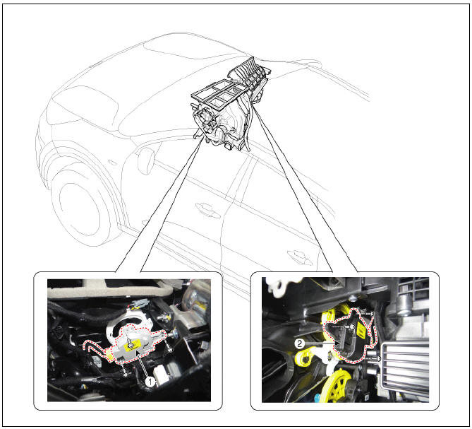
- Remove the driver side shower duct (A) after loosening the screw.
- Install in the reverse order of removal.
Passenger side
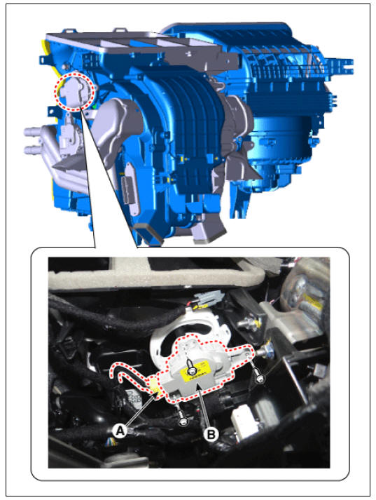
- Disconnect the negative (-) battery terminal.
- Remove the main crash pad assembly.
(Refer to Body - "Main Crash Pad Assembly")
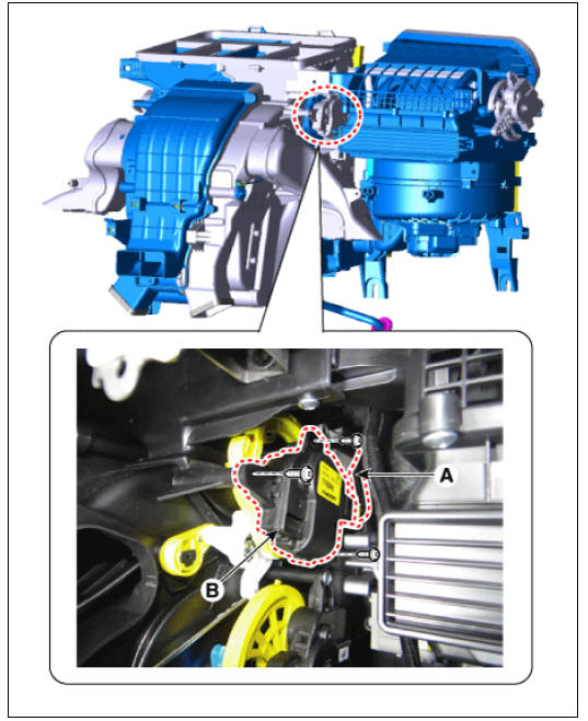
- Disconnect the connector and then remove the mode control actuator (A) after loosening the mounting screws.
- Install in the reverse order of removal.
READ NEXT:
 Auto Defogging Actuator
Description
Installed on the windshield glass, the auto defogging sensor detects humidity
to blow out wind for
defogging to improve visibility and driver comfort. The air conditioner control
module receives a
signal from the sensor and restrai
Emergency Rescue Guide - Introduction/
Identification
Emergency Rescue Guide - Introduction
Document Purpose
The purpose of this document is to familiarize first responders and the
towing/roadside assistance industry with the proper
methods to handle the Niro PHEV in an emergency situation. This gu
SEE MORE:
Piston Pins
Measure the diameter of the piston pin.
Piston pin diameter :
17.997 - 18.000 mm (0.70854 - 0.70866 in.)
Measure the piston pin-to-piston clearance.
Piston pin-to-piston clearance :
0.005 - 0.012 mm (0.00020 - 0.00047 in.)
Chec
Crankshaft Repair procedures
Disassembly
Warning
Be sure to read and follow the "General Safety Information and
Caution" before doing any work related with
the high voltage system. Failure to follow the safety instructions may
result in serious electrical injuries.
Categories
- Home
- KIA Niro EV, Hybrid - Second generation - (SG2) (2021-2024) - Owner's manual
- Kia Niro - First generation - (DE) (2017-2022) - Service and Repair Manual
- Contact Us