KIA Niro: Auto Defogging Actuator
Description
Installed on the windshield glass, the auto defogging sensor detects humidity to blow out wind for defogging to improve visibility and driver comfort. The air conditioner control module receives a signal from the sensor and restrains moisture and eliminates defog by the intake actuator, A/C, auto defogging actuator, blower motor rpm and mode actuator.
Inspection
- Switch "OFF" the ignition.
- Disconnect the auto defogging sensor connector.
- Connect the power (+) terminal to mode actuator connector terminal 3, and ground the negative (-) terminal to terminal 7. Then, inspect that the motor is operated in defrost mode. Reverse the connections to see that it operates in reverse.
- Connect the auto defogging actuator sensor connector.
- Switch "ON" the ignition.
- Check the voltage between terminals 4 and 5.
- -
- -
- OPEN (CW)
- SENSOR REF (+5V)
- Actuator Feed back
- Sensor Ground
- Close (CCW)
Specification
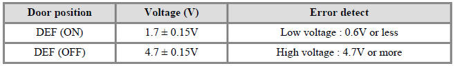
It will feedback the current position of the actuator to controls.
- If the measured voltage does not satisfy the specifications, replace with a genuine auto defogging actuator.
- Replace the auto defogging actuator if it is proved that there is a problem with it.
Replacement
- Disconnect the negative (-) battery terminal.
- Remove the glove box housing.
(Refer to Body - "Glove Box Housing".)
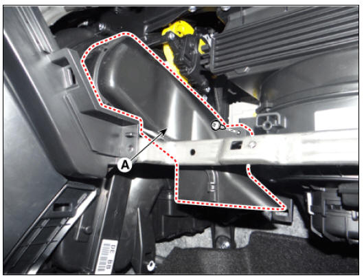
- Loosen the mounting screw and remove the passenger seat shower duct (A).
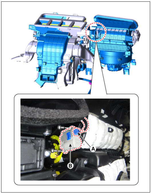
- Disconnect the connector and then remove the auto defogging actuator (A) after loosening the screws.
- Install in the reverse order of removal.
Description
In ordinary cars, the mechanical water pump mounted on the engine for heating purposes is activated to circulate the cooling water, but in hybrid cars, AWEP is used to circulate the cooling water when the engine is not operating.
Removal
- Remove the battery (-) terminal.
- Remove the engine room under cover.
(Refer to Engine Mechanical System - "Engine Room Under Cover")
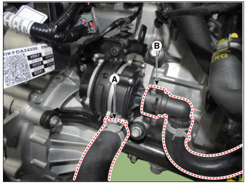
- Remove the heater hose (A) and AEWP hose (B).
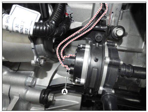
- Disconnect the lock pin to remove the heater hose pump connector (A).
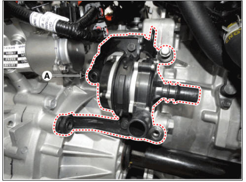
- Loosen the mounting bolts and remove the AEWP (A).
Tightening torque : 18.6 - 21.6 N.m (1.9 - 2.2 kgf.m, 13.7 - 15.9 Ib-ft)
Installation
- Install in the reverse order of removal.
Warning
- Be careful not to damage other hoses nearby when tightening the clamp.
- Install the clamp in the specified direction to prevent interference with surrounding components.
- The cooling system should be refilled with the coolant after
replacing the AEWP.
(Refer to Engine Mechanical System - "Coolant ")
- After installing, check for leakage of coolant or fluid from hose connection during engine start.
READ NEXT:
 Emergency Rescue Guide - Introduction/
Identification
Emergency Rescue Guide - Introduction/
Identification
Emergency Rescue Guide - Introduction
Document Purpose
The purpose of this document is to familiarize first responders and the
towing/roadside assistance industry with the proper
methods to handle the Niro PHEV in an emergency situation. This gu
SEE MORE:
Front Lower Arm Repair procedures
Front Lower Arm Components and components location
Components
Ball joint assembly
Front lower arm assembly
Front Lower Arm Repair procedures
Removal
Remove the wheel and tire.
Tightening torque:
107.9 - 127.5 N*m (11.0 - 13.0 k
Heated Steering wheel
Description
When manually selected, the heated steering wheel system improves the thermal
comfort of the driver
by heating the steering wheel.
Specifications
System Circuit Diagram
Terminal Function
Inspection
NTC characteris
Categories
- Home
- KIA Niro EV, Hybrid - Second generation - (SG2) (2021-2024) - Owner's manual
- Kia Niro - First generation - (DE) (2017-2022) - Service and Repair Manual
- Contact Us