KIA Niro: Oil Cooler Repair procedures | Oil Pressure Switch Repair procedures
Removal
- Remove the engine room under cover.
(Refer to Engine and Transaxle Assembly - "Engine Room Under Cover")
- Drain the engine oil and then remove the oil filter.
(Refer to Lubrication System - "Engine Oil")
- Drain the coolant.
(Refer to Cooling System - "Coolant")
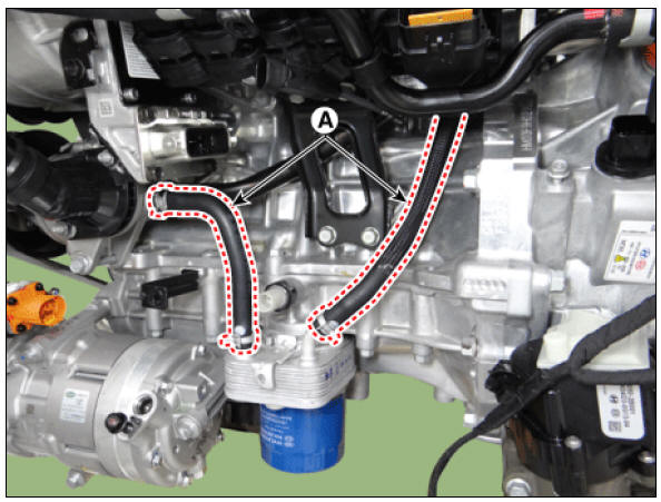
- Disconnect the coolant hose (A).
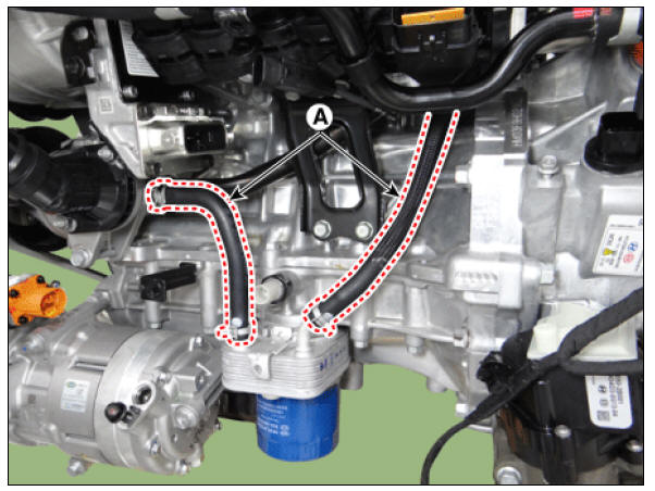
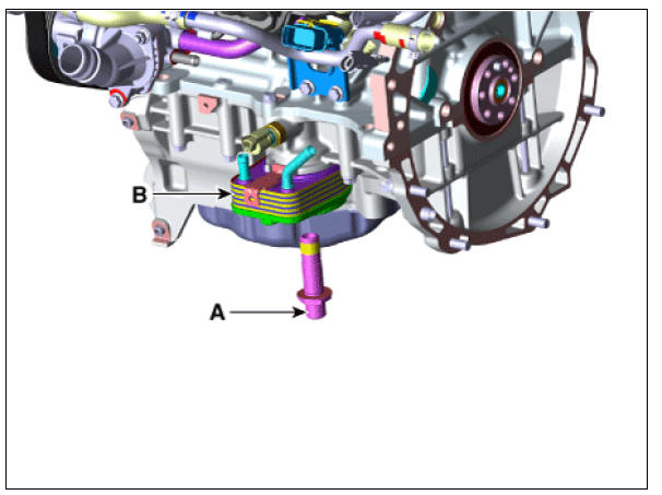
- Unfasten the fixing bolt (A) and then remove the oil cooler assembly (B).
Installation
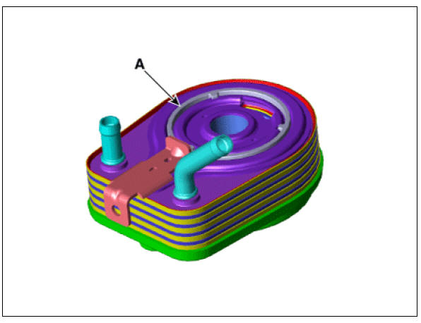
- Apply engine oil to the oil cooler packing surface (A).
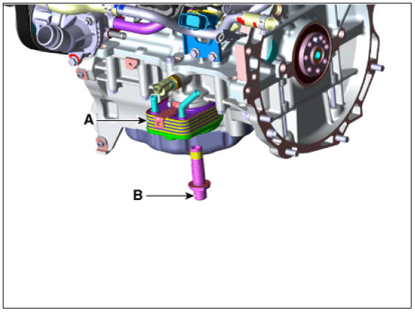
- Install the oil cooler (A) with a fixing bolt (B).
Tightening torque : 50.1 - 55.9 N*m (5.1 - 5.7 kgf*m, 36.9 - 41.2 lb*ft)
Warning
Fix position of oil cooler stopper where oil cooler resists on ladder frame stopper.
- Connect the coolant hose (A).
- Fill the coolant.
(Refer to Cooling System - "Coolant")
- Install the oil filter and then fill the engine oil.
(Refer to Lubrication System - "Engine Oil")
- Install the engine room under cover.
(Refer to Engine and Transaxle Assembly - "Engine Room Under Cover")
Oil Pressure Switch Repair procedures
Removal and
Installation
- Disconnect the battery negative terminal.
- Remove the engine room under cover.
(Refer to Engine and Transaxle Assembly - "Engine Room Under Cover")
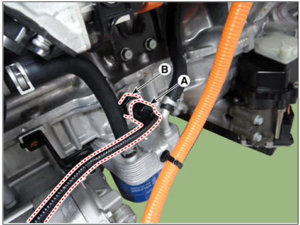
- Disconnect the oil pressure switch connector (A).
- Remove the oil pressure switch (B).
Tightening torque : 9.8 - 11.8 N*m (1.0 - 1.2 kgf*m, 7.2 - 8.7 lb*ft)
- Install in the reverse order of removal.
Warning
When installing the oil pressure switch, apply seal lock to the thread.
Seal lock : THREEBOND 2403
Thickness : 0.2 - 0.4 mm (0.008 - 0.016 in.) 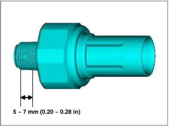
Inspection
- Check the continuity between the terminal and the body with an ohmmeter.
If there is no continuity, replace the oil pressure switch.
- Check the continuity between the terminal and the body when the fine wire is pushed. If there is continuity even when the fine wire is pushed, replace the switch.
- If there is no continuity when a pressure of 50 kPa (0.50 kgf/cm², 7.25 psi) is applied through the oil hole, the switch is operating properly.
Check for air leakage. If air leaks, the diaphragm is broken. Replace it.
Oil Level Gauge & Pipe Repair procedures
Removal and
Installation
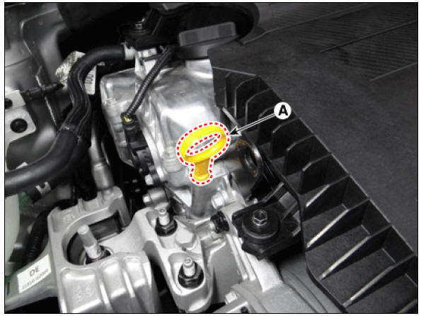
- Remove the oil level gauge (A).
- Remove the timing chain cover.
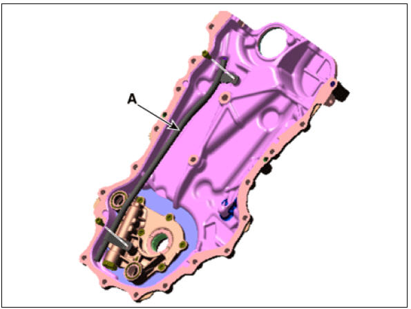
(Refer to Timing System - "Timing Chain Cover") 3. Remove the Oil level gauge pipe (A).
Tightening torque : 8.8 - 13.7 N*m (0.9 - 1.4 kgf*m, 6.5 - 10.1 lb*ft)
- Install in the reverse order of removal.
Removal and
Installation
Warning
Do not disassemble the oil pump (A) from timing chain cover because it is supplied as timing chain cover & oil pump assembly. 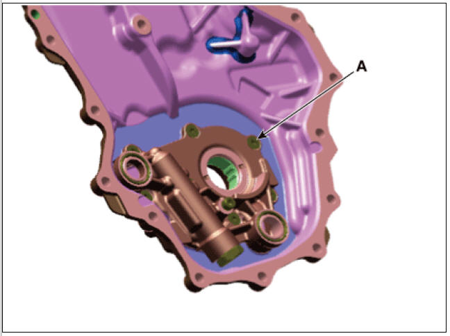
READ NEXT:
 Front Oil Seal Repair procedures | Timing Chain Cover Repair procedures
Components
Front oil seal
Timing chain cover
Variable force solenoid (VFS) valve
O-ring
Timing chain tensioner
Timing chain tensioner arm
Timing chain guide
Timing chain
Timing chain cam guide
Front
SEE MORE:
Power Door Lock Module Repair procedures
Inspection
Warning
When removing with a flat-tip screwdriver or remover, wrap
protective tape around the tools to
prevent damage to components.
When removing the interior trim pieces, use a plastic panel
removal tool not to damage the
Power Door Locks
Power Door Locks / Components And Components Location
Driver power window switch
Assist power window switch
Integrated Gateway & Power control Module (IGPM)
Door lock knob
Tailgate latch assembly
Door latch assembly
Door lock/
Categories
- Home
- KIA Niro EV, Hybrid - Second generation - (SG2) (2021-2024) - Owner's manual
- Kia Niro - First generation - (DE) (2017-2022) - Service and Repair Manual
- Contact Us