KIA Niro: Front Oil Seal Repair procedures | Timing Chain Cover Repair procedures
Components
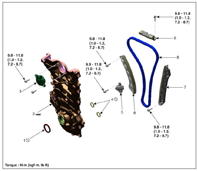
- Front oil seal
- Timing chain cover
- Variable force solenoid (VFS) valve
- O-ring
- Timing chain tensioner
- Timing chain tensioner arm
- Timing chain guide
- Timing chain
- Timing chain cam guide
Front Oil Seal Repair procedures
Replacement
- Remove the crankshaft damper pulley.
(Refer to Drive Belt System - "Crankshaft Damper Pulley")
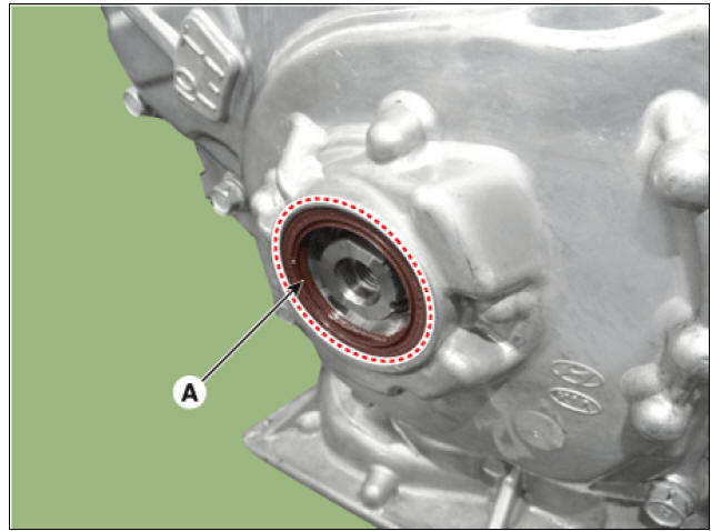
- Remove the front oil seal (A).
- Apply engine oil to a new oil seal lip & outer surface.
Warning
Remove any debris from the lip portion of the oil seal.
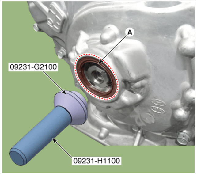
- Using the SSTs (09231-G2100, 09231-H1100), install the front oil seal (A).
Warning
Always use new oil seal.
- Install the crankshaft damper pulley.
(Refer to Drive Belt System - "Crankshaft Damper Pulley")
Timing Chain Cover Repair procedures
Removal
Warning
- Be sure to read and follow the "General Safety Information and Caution" before doing any work related with the high voltage system. Failure to follow the safety instructions may result in serious electrical injuries.
- Be sure to shut off the high voltage circuit according to the "High Voltage Shut-off Procedures" before doing any work related with the high voltage system to avoid serious electrical injuries.
Warning
- Use fender covers to avoid damaging painted surfaces.
- To avoid damage, unplug the wiring connectors carefully while holding the connector portion.
- To release the fuel system pressure before removing the engine assembly, start the engine with the fuel pump relay removed. And then turn off the ignition switch after engine stops.
Warning
Mark all wiring and hoses to avoid misconnection.
- Shut off the high voltage circuit.
(Refer to Engine Mechanical System - "High Voltage Shut off Procedure")
- Remove the air cleaner.
(Refer to Intake and Exhaust System - "Air Cleaner")
- Remove the RH front wheel.
(Refer to Suspension System - "Wheel")
- Remove the engine room under cover.
(Refer to Engine and Transaxle Assembly - "Engine Room Under Cover")
- Drain the engine oil.
(Refer to Lubrication System - "Engine Oil")
- Drain the engine coolant.
(Refer to Cooling System - "Coolant")
- Remove the drive belt.
(Refer to Drive Belt System - "Drive Belt")
- Remove the drive belt tensioner.
(Refer to Drive Belt System - "Drive Belt Tensioner")
- Remove the idler.
(Refer to Drive Belt System - "Idler")
- Remove the crankshaft damper pulley.
(Refer to Drive Belt System - "Crankshaft Damper Pulley")
- Remove the water pump.
(Refer to Cooling System - "Water Pump")
- Remove the cylinder head cover.
(Refer to Cylinder Head Assembly - "Cylinder Head Cover")
- Remove the oil pan.
(Refer to Lubrication System - "Oil Pan")
- Remove the engine mounting support bracket.
(1) Install the jack under the edge of the ladder frame to support the engine.
Warning
Put the rubber block between jack and ladder frame to avoid damaging the ladder frame.
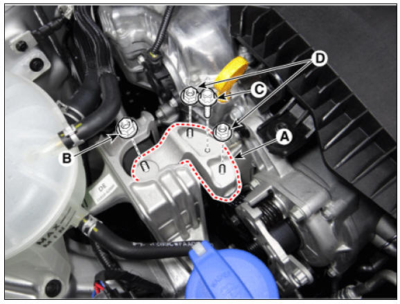
(2) Remove the engine mounting support bracket (A).
Tightening torque
Nut (B) :
88.3 - 107.9 N*m (9.0 - 11.0 kgf*m, 65.1 - 79.6 lb*ft)
Bolt (C) and nuts (D) :
58.8 - 73.5 N*m (6.0 - 7.5 kgf*m, 43.3 - 54.2 lb*ft)
Warning
Do not reuse the bolt C, which is special bolt coated with bond.
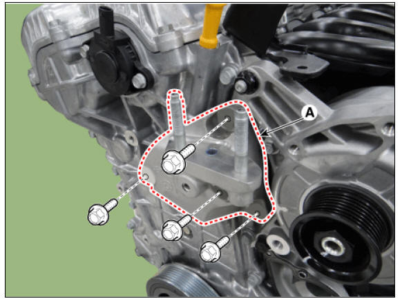
- Remove the engine support bracket (A).
Tightening torque : 39.2 - 44.1 N*m (4.0 - 4.5 kgf*m, 28.9 - 32.5 lb*ft)
- Remove the oil level gauge.
(Refer to Lubrication System - "Oil Level Gauge & Pipe")
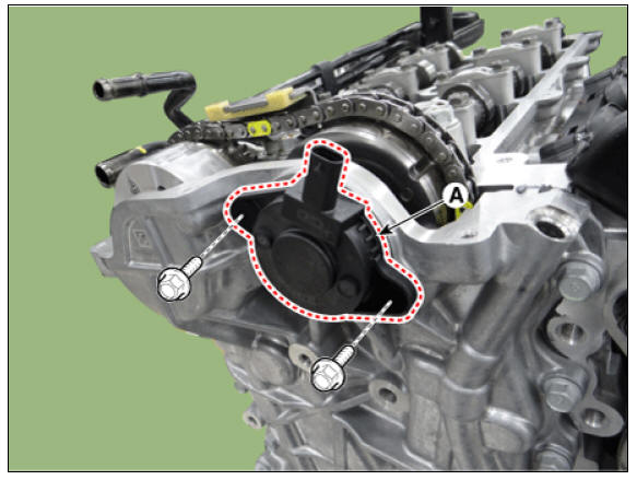
- Remove the variable force solenoid (VFS) valve (A).
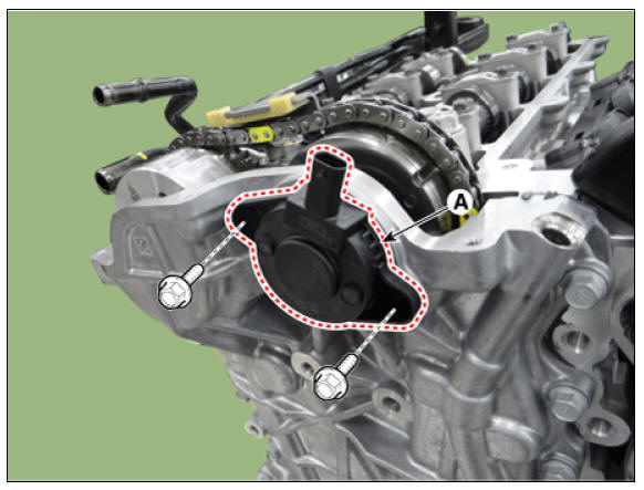
Warning
It must removing the variable force solenoid (VFS) valve before removing the timing chain cover.
- Remove the timing chain cover (A).
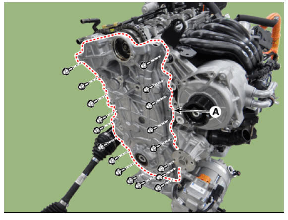
Warning
- Remove thoroughly sealant and oil etc left at the sealing surface after remove the chain cover and oil pan. (If any impurities are left at the sealing face, oil may leak after reassembly even with the sealant application.)
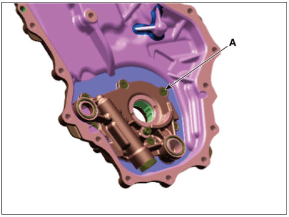
- Do not disassemble the oil pump (A) from timing chain cover because it is supplied as timing chain cover & oil pump assembly.
Installation
- Install the timing chain cover (A).
(1) Using a gasket scraper, remove all the old packing material from the gasket surfaces.
(2) The sealant locations on the chain cover and the counter parts (cam carrier, cylinder head, cylinder block, and lower crankcase) must be free of harmful foreign materials, oil, dust and moisture. Spray cleaner on the surface and wipe with a clean duster.
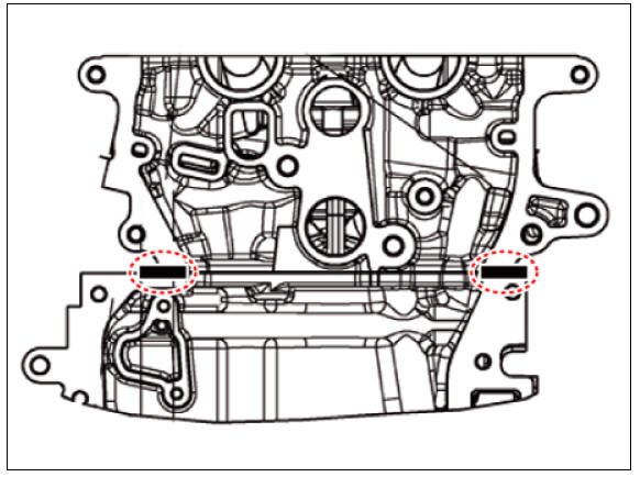
(3) Before assembling the timing chain cover, liquid sealant should be applied on the gap between cam carrier, cylinder head and cylinder block.
Bead width : 3.0 - 5.0 mm (0.11 - 0.20 in.) Sealant : Threebond 1217H or equivalent
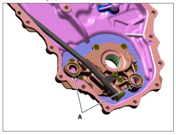
(4) Install the new O-ring (A).
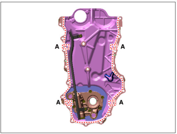
(5) After applying liquid sealant on the timing chain cover, assemble the cover within 5 minutes of applying sealant. Continuous bead of sealant should be applied to prevent any path from oil leakage.
Bead width :
Whole section: 2.5 - 3.5 mm (0.10 - 0.14 in.)
Section : 3.5 - 4.5 mm (0.14 - 0.18 in.)
Sealant : Threebond 1217H or equivalent
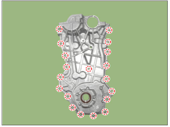
(6) Install the timing chain cover. The dowel pins on the cylinder block and holes on the timing chain cover should be used as a reference for assembling the timing chain cover to the exact position.
Tightening torque : 18.6 - 23.5 N*m (1.9 - 2.4 kgf*m, 13.7 - 17.4 lb*ft)
Warning
It is not recommended to start the engine or perform pressure test within 30 minutes of assembling the timing chain cover.
- Install the variable force solenoid (VFS) valve (A).
Tightening torque : 9.8 - 11.8 N*m (1.0 - 1.2 kgf*m, 7.2 - 8.7 lb*ft)
Warning
- Do not use any dropped variable force solenoid (VFS) valve.
- Note below cautions when installing variable force solenoid (VFS) valve.
1) After replacing the O-ring (A) of variable force solenoid (VFS) valve, apply engine oil on new O-ring (A). 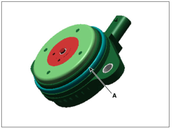
2) Push variable force solenoid (VFS) valve up to the timing chain cover, and temporarily tighten the bolt.
3) Tighten the variable force solenoid (VFS) valve to the specified torque.
- Replace the front oil seal if necessary.
(Refer to Timing System - "Front Oil Seal")
- Install the remaining parts in the reverse order of removal.
- Connect the high voltage circuit.
(Refer to Engine Mechanical System - "High Voltage Shut off Procedure")
- Add all the necessary fluids and check for leaks. Connect KDS. Check for codes, note, and clear. Recheck
Warning
- Refill engine with engine oil.
- Clean battery posts and cable terminals and assemble (12 Volt only).
- Inspect for fuel leakage.
- After assembling the fuel line, switch on the ignition (without operating the starter) so that the fuel pump runs for approximately two seconds and fuel line pressurizes.
- Repeat this operation two to three times, then check for fuel leakage at any point in the fuel line.
READ NEXT:
 Timing Chain Repair procedures
Removal
Warning
Be sure to read and follow the "General Safety Information and
Caution" before doing any work related
with the high voltage system. Failure to follow the safety instructions may
result in serious electrical
injuries.
SEE MORE:
Charging the electric vehicle (Abrupt stop)
Action to be taken when charging
stops abruptly
When the high voltage battery does not
charge, check the followings:
Check the charging setting for the
vehicle. Refer to "EV settings" (e.g. When scheduled charging is
set, c
Intelligent Speed Limit Assist settings
Speed limit
A: Driver Assistance
Speed Limit
Speed Limit Assist
Speed Limit Warning
Off
With the vehicle on, touch Settings →
Driver Assistance → Speed Limit on
the instrument cluster or Settings →
Vehicle → Driver As
Categories
- Home
- KIA Niro EV, Hybrid - Second generation - (SG2) (2021-2024) - Owner's manual
- Kia Niro - First generation - (DE) (2017-2022) - Service and Repair Manual
- Contact Us