KIA Niro: Crash Pad Main Lower Panel
Kia Niro - First generation - (DE) (2017-2022) - Service and Repair Manual / Body (Interior And Exterior) / Crash Pad / Crash Pad Main Lower Panel
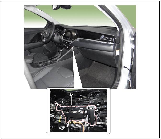
- Crash pad main lower panel
Replacement
Warning
Put on gloves to protect your hands.
Warning
- Use a plastic panel removal tool to remove interior trim pieces without marring the surface.
- Be careful not to bend or scratch the trim and panels.
- Disconnect the negative (-) battery terminal.
- Remove the floor console assembly.
(Refer to Floor Console - "Floor Console Assembly")
- Remove the cluster fascia panel.
(Refer to Crash Pad - "Cluster Fascia Panel")
- Remove the glove box housing.
(Refer to Crash Pad - "Glove Box Housing")
- Remove the center fascia lower panel.
(Refer to Crash Pad - "Center Fascia Panel")
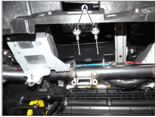
- Separate the heater control unit (A) after loosening the screws.
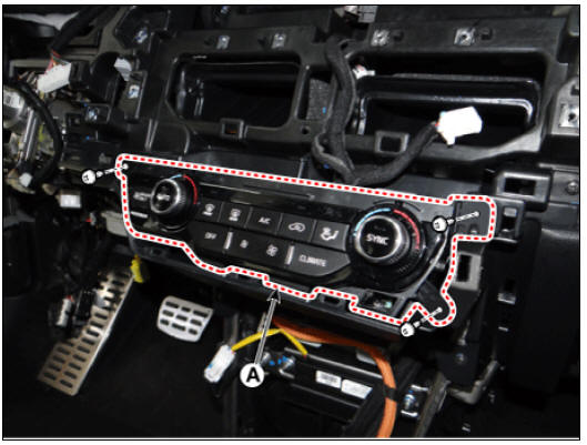
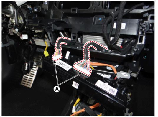
- Remove the heater control unit (B) after disconnecting the connector (A).
- Remove the crash pad main lower panel (A) after loosening the nut & screws.
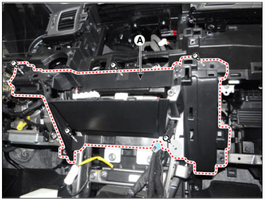
- Install in the reverse order of removal.
Warning
- Make sure the connectors are connected properly.
- Replace any damaged clips.
Crash pad main lower panel
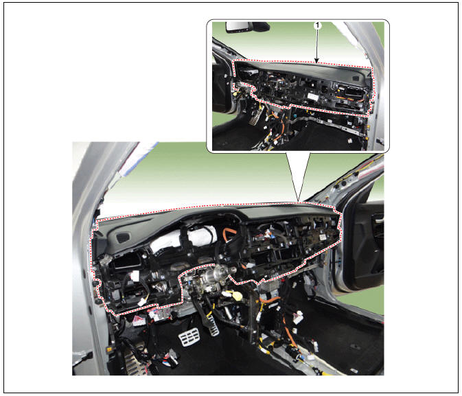
- Crash pad main lower panel
Replacement
- Remove the front seat.
(Rear to Front Seat - "Front Seat Assembly")
- Remove the front pillar trims on both sides.
(Refer to Body - "Front Pillar Trim")
- Remove the center fascia panel.
(Refer to Crash Pad - "Crash Pad Center Panel")
- Remove the steering wheel.
(Refer to Steering System - "Steering Wheel")
- Remove the instrument cluster.
(Refer to Body Electrical System - "Instrument Cluster")
- Remove the multifunction switch assembly.
(Refer to Body Electrical System - "Multifunction Switch")
- Remove the steering column shroud lower panel.
(Refer to Crash Pad - "Steering Column Shroud Panel")
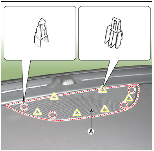
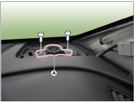
- Remove the center speaker grille (A) by using a remover.
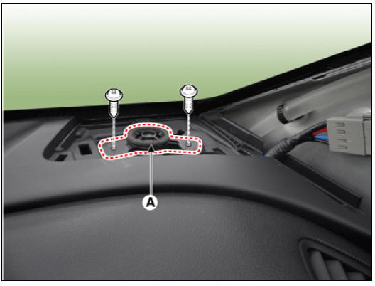
- Separate the center speaker (A) after loosening the screws.
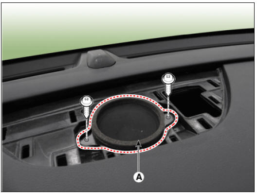
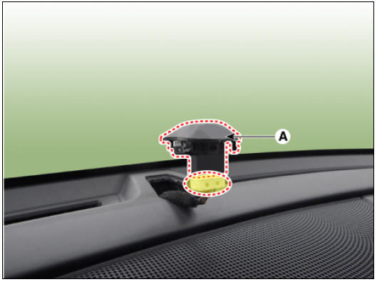
- Remove the center speaker (B), after disconnecting the connector (A).
- Remove the mid-range speaker grilles (A) on both sides by using a remover.
- Separate the mid-range speakers (A) on both sides after loosening the mounting bolts.
- Remove the mid-range speakers (B) on both sides after disconnecting the connector (A).
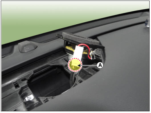
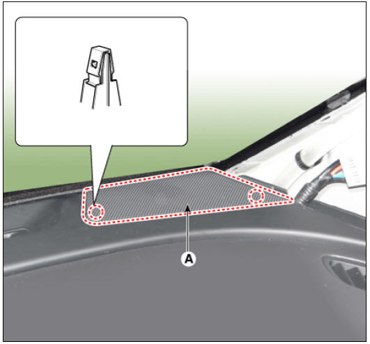
- Separate the photo sensor (A) by using a remover.
- Loosen the passenger airbag mounting bolts (A).
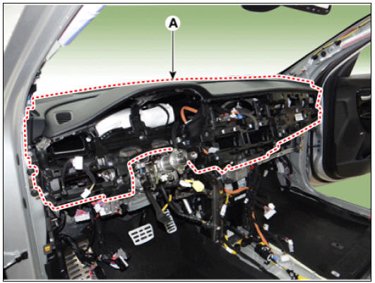
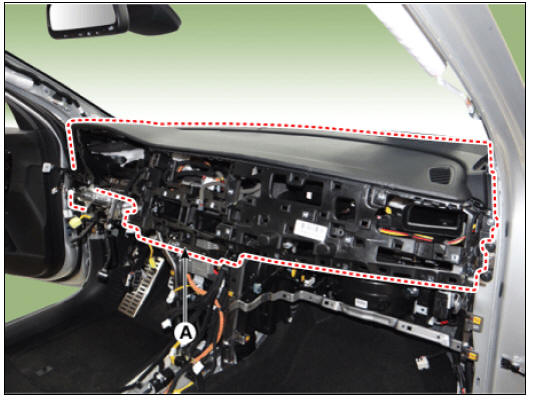
- Separate the main crash pad assembly (A) after loosening the mounting bolts and nuts.
LH
RH
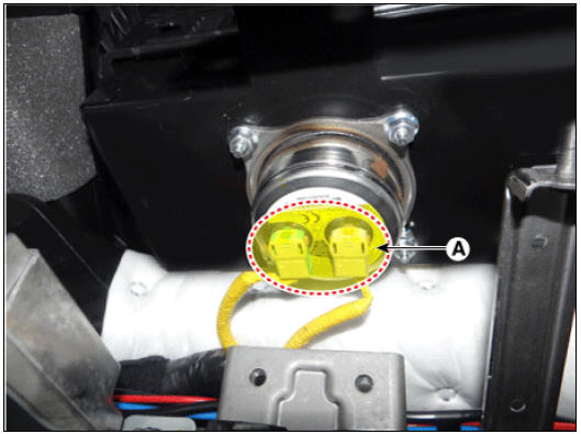
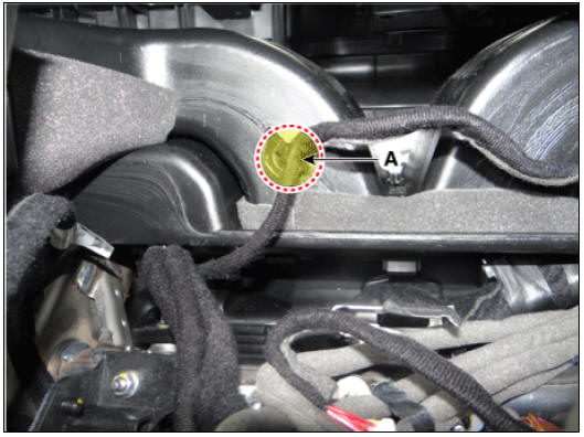
- Disconnect the passenger airbag connector (A).
- Remove the crash pad assembly after disconnecting the wiring clip (A).
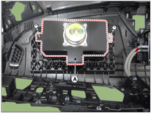
- Remove the passenger airbag (A) after loosening the bolts.
- Install in the reverse order of removal.
Warning
- Make sure the crash pad fits onto the guide pins correctly.
- Before tightening the bolts, make sure the crash pad wire harnesses are not pinched.
- Make sure the connectors are plugged in properly, and the antenna lead is connected properly.
- Enter the anti-theft code for the radio, then enter the customer's radio station presets.
READ NEXT:
 Cowl Cross Bar Assembly
Cowl cross bar assembly
Replacement
Remove the cowl top cover.
(Refer to Cowl Top Cover - "Repair procedures")
Remove the main crash pad assembly.
(Refer to Crash Pad - "Main Crash Pad Assembly")
Remove the c
Fender
Fender assembly
Fender / Repair Procedures
Replacement
Warning
Be careful not to damage the fender and body.
Use a plastic panel removal tool to remove interior trim pieces
without marring the surface.
Remove the head
Floor Carpet
Floor Carpet / Repair Procedures
Replacement
Warning
Put on gloves to protect your hands.
Warning
Use a plastic panel removal tool to remove interior trim pieces
without marring the surface.
Be careful not to bend or scratch the tr
SEE MORE:
Front Hub / Knuckle
Components
Brake disc
Hub assembly
Dust cover
Knuckle
Front Hub / Knuckle / Repair Procedures
Removal
Remove the wheel and tire.
Tightening torque :
107.9 - 127.5 N*m (11.0 - 13.0 kgf*m, 79.6 - 94.0 lb*ft)
Warning
Be c
Cleaning
Make sure the ignition switch and all accessories are in the OFF
position.
Remove the battery from the vehicle.
(Refer to Charging System - "Battery")
Warning
Care should be taken in the event the battery case is cracked or
Categories
- Home
- KIA Niro EV, Hybrid - Second generation - (SG2) (2021-2024) - Owner's manual
- Kia Niro - First generation - (DE) (2017-2022) - Service and Repair Manual
- Contact Us