KIA Niro: Low Voltage DC/DC Converter
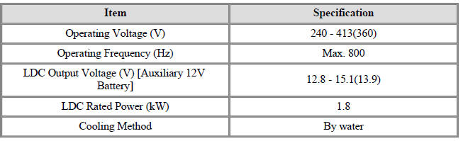
Specification
Description
The Low Voltage DC/DC is integrated into the HPCU. It charges the auxiliary
battery as a substitute
for generator by converting the high voltage (DC 270V) from the high voltage
battery into low voltage
(DC 12V).
Component Location
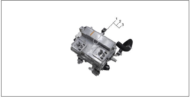
- Low Voltage DC/DC Converter (LDC) (HPCU)
- Low Voltage DC/DC Converter (LDC) power output terminal (+) (DC 12V)
- Low Voltage DC/DC Converter (LDC) ground terminal (-)
Schematic Diagram
Removal
Warning
- Be sure to read and follow the "General Safety Information and Caution" before doing any work related with the high voltage system. Failure to follow the safety instructions may result in serious electrical injuries.
- Be sure to read and follow the "High Voltage Shut-off
Procedures" before doing any work related with the high voltage system.
Failure to follow the safety instructions may result in serious electrical injuries.
- Shut off the high voltage.
(Refer to "High voltage Shut-off Procedures")
- Remove the air cleaner assembly and air duct.
(Refer to Engine Mechanical System - "Air Cleaner")
- Remove the ECM & TCM bracket assembly.
(Refer to Engine Control/Fuel System - "Engine Control Module")
- Drain the coolant of hybrid motor cooling system.
(Refer to Hybrid Motor Cooling System - "Coolant")
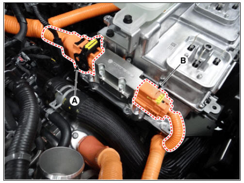
- Disconnect the motor power cable connector (A) and HSG power cable connector (B) after loosening the mounting bolts.
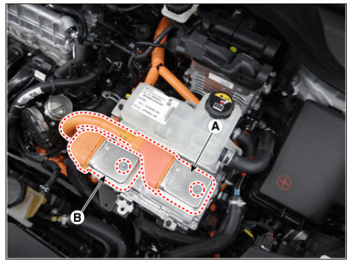
- Disconnect the power cable (A) and inverter power cable (B) from the HPCU.
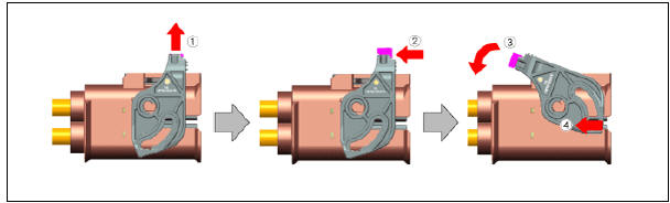
Warning
Remove the inverter power cale in the follwing order.
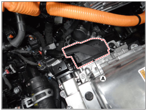
- Disconnect the HCU & inverter (MCU) connector (A).
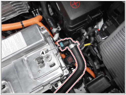
- Disconnect the coolant outlet hose & pipe after loosening the mounting bolt (A).
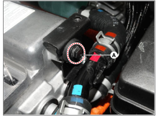
- Disconnect the coolant inlet hose quick-connector (A).
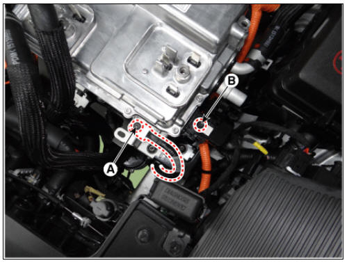
- Remove the LDC power outlet cable mounting bolt (A) and ground cable bolt (B).
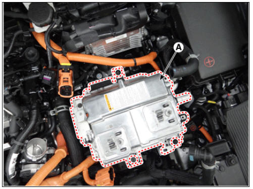
- Remove the HPCU (A) after loosening the mounting bolts.
Installation
Warning
- Be sure to read and follow the "General Safety Information and Caution" before doing any work related with the high voltage system. Failure to follow the safety instructions may result in serious electrical injuries.
- Be sure to read and follow the "High Voltage Shut-off
Procedures" before doing any work related with the high voltage system.
Failure to follow the safety instructions may result in serious electrical injuries.
- Install the LDC in the reverse order of removal.
- Refill the hybrid motor cooling system coolant and perform air bleeding
by using the KDS.
(Refer to Hybrid Motor Cooling System - "Coolant")
Warning
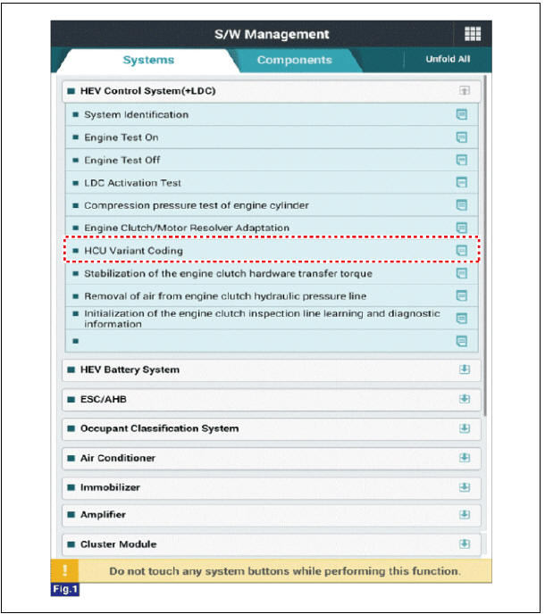
Perform HCU Variant Coding and Engine Clutch / Motor Resolver learning after replacing the HPCU.
HCU Variant Coding
- Turn the ignition switch OFF.
- Connect the KDS to Data Link Connector (DLC).
Turn the ignition switch ON.
- Select "Vehicle, Model year, Engine, System".
- Select "Vehicle S/W Management".
- Select "HCU Variant Coding".
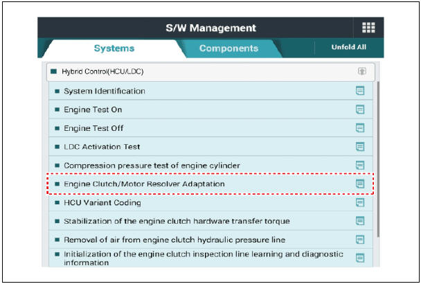
Engine clutch/motor resolver adaptation
- Turn the ignition switch OFF.
- Connect the KDS to Data Link Connector (DLC).
Turn the ignition switch ON.
- Select "Vehicle, Model year, Engine, System".
- Select "Vehicle S/W Management".
- Select "Engine clutch/motor resolver adaptation.".
READ NEXT:
 Power Cable
Components
Power Cable (HPCU↔Main High Voltage Battery
System)
Power Cable (HPCU↔HSG, Electric /C Compressor)
Power Cable (Main High Voltage Battery System ↔ Sub
High Voltage Battery System)
Removal
Warning
Power Cable (HPCU-HSG, Electric /C Compressor). Main High Voltage Battery System, Sub High Voltage Battery System
Turn ignition switch OFF and disconnect the negative (-) battery cable.
Shut off the high voltage.
(Refer to "High voltage Shut-off Procedures")
Disconnect the motor power cable connector (A) and HSG p
SEE MORE:
Front View Camera Unit - Removal
Inspection
In the body electrical system, failure can be quickly diagnosed by using
the vehicle diagnostic system (KDS).
The diagnostic system (KDS) provides the following information.
(1) Self diagnosis : Checking failure and code number
How to connect portable charger (ICCB: In-Cable Control Box)
Connect the plug to a household electric
outlet.
A: Plug
B: Electric Outlet
Check if the power lamp (green)
appears on the control box.
Depress the brake pedal and apply
the parking brake.
Turn OFF all switches,
Categories
- Home
- KIA Niro EV, Hybrid - Second generation - (SG2) (2021-2024) - Owner's manual
- Kia Niro - First generation - (DE) (2017-2022) - Service and Repair Manual
- Contact Us