KIA Niro: Power Cable (HPCU-HSG, Electric /C Compressor). Main High Voltage Battery System, Sub High Voltage Battery System
Kia Niro - First generation - (DE) (2017-2022) - Service and Repair Manual / Hybrid Control System / Power Cable / Power Cable (HPCU-HSG, Electric /C Compressor). Main High Voltage Battery System, Sub High Voltage Battery System
- Turn ignition switch OFF and disconnect the negative (-) battery cable.
- Shut off the high voltage.
(Refer to "High voltage Shut-off Procedures")
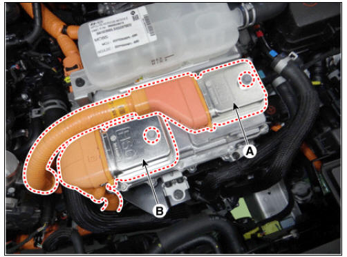
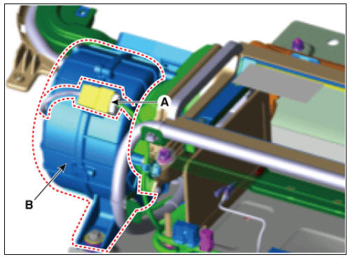
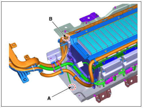
- Disconnect the motor power cable connector (A) and HSG power cable connector (B) after loosening the mounting bolts.
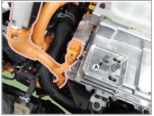
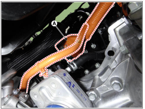
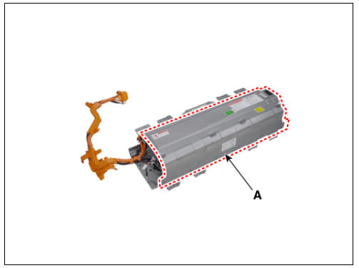
- Disconnect the inverter power cable (A) from the HPCU.
Warning
Remove the inverter power cale in the follwing order. 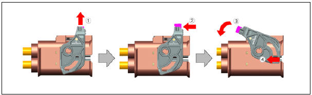
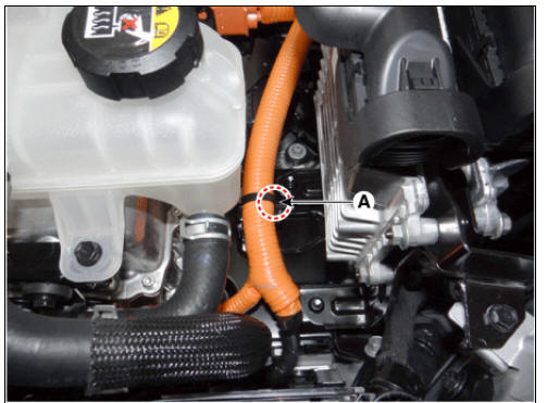
- Disconnect the clamp (A).
- Lift the vehicle.
- Remove the engine room under cover.
(Refer to Engine Mechanical System - "Engine Room Under Cover")
- Disconnect the power cable (A) from the electric A/C compressor.
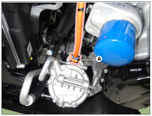
- Disconnect the power cable (A) from the HSG.
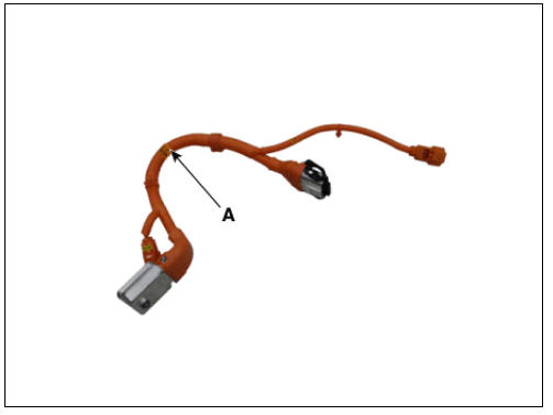
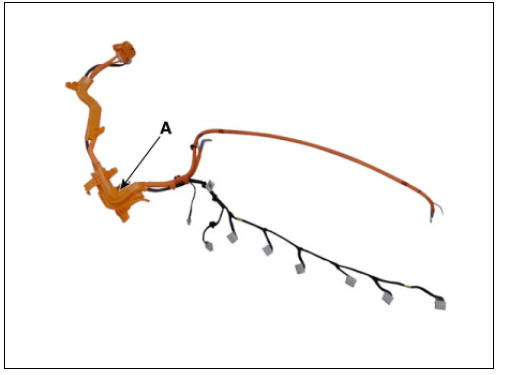
- Remove the power cable (A).
Power Cable (Main High Voltage Battery System - Sub High Voltage Battery System)
- Turn ignition switch OFF and disconnect the negative (-) battery cable.
- Shut off the high voltage.
(Refer to "High voltage Shut-off Procedures")
- Remove the main high voltage battery system assembly.
(Refer to High Voltage Battery System - "Removal")
- Remove the high voltage battery cover (A) after loosening the mounting bolt.
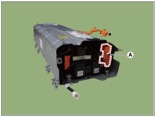
- Remove the high voltage battery front cover (A).
- Disconnect the cooling fan connector (A).
- Remove the cooling fan (B) after loosening the mounting bolts.
Cooling Fan mounting bolt : 7.8 - 11.8 N*m (0.8 - 1.2 kgf*m, 5.8 - 8.7 lb*ft)
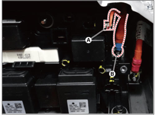
- Disconnect the battery current sensor connector (A).
- Disconenct the high voltage power cable (-) terminal (B) after loosening the mounting nut.
- Disconnect the cell monitoring unit connector (A).
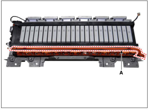
- Remove the ground bolt (A) and high voltage cable (-) terminal (B).
- Remove the power cable (A).
Installation
Warning
- Be sure to read and follow the "General Safety Information and Caution" before doing any work related with the high voltage system. Failure to follow the safety instructions may result in serious electrical injuries.
- Be sure to read and follow the "High Voltage Shut-off Procedures" before doing any work related with the high voltage system.
Failure to follow the safety instructions may result in serious electrical injuries.
- Install in the reverse order of removal.
Description
Plug-in hybrid vehicle can be normal charge.
In the case of normal charge, the battery is charged after 220V AC power is transformed to DC power
by On-Board Charger (OBC).
While charging the vehicle, the driving of the vehicle is restricted.
READ NEXT:
 ON-Board Charger (OBC)
HPCU (Hybrid Power Control Unit)
ON-Board Charger (OBC)
Normal Chage Port
Power Cable (HPCU↔HSG, Electric /C Compressor)
Power Cable (HPCU↔Main High Voltage Battery System)
Power Cable (
Normal charging port
Removal
Warning
Be sure to read and follow the "General Safety Information and
Caution" before doing any work related
with the high voltage system. Failure to follow the safety instructions may
result in serious electrical
in
SEE MORE:
Rear Seat Assembly | Rear Seat Back Cover
Rear seat back assembly
Rear seat cushion covering
Rear seat cushion pad
Rear seat cushion heater
Rear seat armrest
Rear seat back covering
Rear seat back pad
Rear seat back frame
Rear seat headrest guide
AHB(Active Hydraulic Boost) System / Description And Operation
Description
Regeneration Brake System
During deceleration or braking of an electric vehicle or HEV, the drive motor
acts as an alternator and charges the battery by
converting the vehicle's kinetic energy generated during braking into electrical
Categories
- Home
- KIA Niro EV, Hybrid - Second generation - (SG2) (2021-2024) - Owner's manual
- Kia Niro - First generation - (DE) (2017-2022) - Service and Repair Manual
- Contact Us