KIA Niro: Lumbar Support Units
Kia Niro - First generation - (DE) (2017-2022) - Service and Repair Manual / Body Electrical System / Seat Heater / Lumbar Support Units
Removal
- Disconnect the negative (-) battery terminal.
- Remove the front seat back cover.
(Refer to Body - "Front Seat Back Cover")
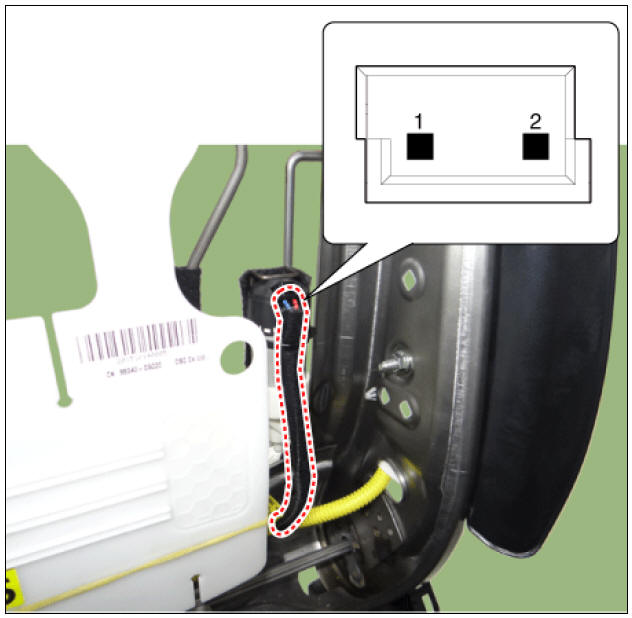
- Disconnect the lumbar support motor connector (A).
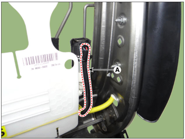
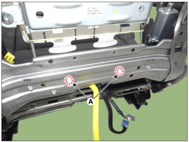
- Separate the retaining clips (A) from the seat frame.
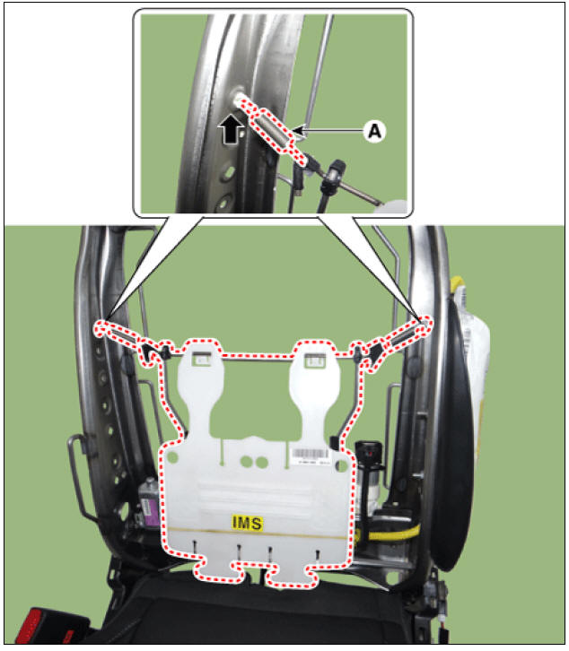
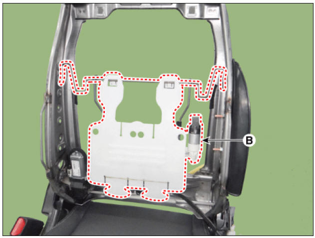
- Remove the lumbar support assembly (B) after disengaging mounting clip (A).
Installation
- Install in the reverse order of removal.
Warning
- Make sure that the connectors are plugged in properly.
- Check the lumbar support system.
Inspection
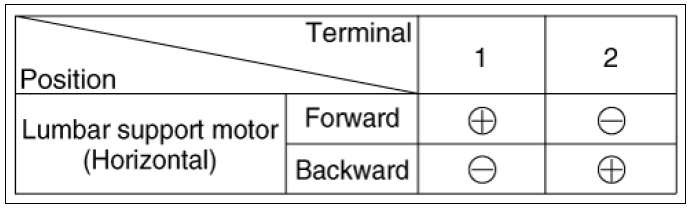
Lumbar Support Motor
- Disconnect the connectors for motor.
- When the battery power is supplied to the motor connector, check the motor for smooth operation.
- Reverse the connections and check that the motor turns in reverse.
- If the motor runs abnormally, replace it.
READ NEXT:
 Smart Key System
Specifications
Smart Key Unit
RF Receiver
Smart Key
Antenna
Smart Key System / Components And Components Location
Component Location (1)
Smart key unit (SMK)
Interior antenna 1
Interior antenna 2
Buzzer
Door outsid
Smart Key System / Description And Operation
Description
The SMART KEY system is a system that allows the user to access and operate a
vehicle in a very
convenient way. To access the vehicle, no traditional key or remote control unit
is needed.
The user carries a SMART KEY FOB which do
Smart Key Repair procedures, Smart Key Unit
Adjustment
Smart Key Code Saving
Connect the VCI II in driver side crash pad lower panel, turn the power on KDS.
Select the vehicle model and then do "Smart key code saving".
After selecting "Smart Key Code
SEE MORE:
Engine compartment
(Kia NIRO Hybrid)
Smartstream G1.6 GDi HEV
Smartstream G1.6 GDi PHEV
Engine coolant reservoir
Brake fluid reservoir
Air cleaner
Engine oil filler cap
Engine oil dipstick
Windshield washer fluid reservoir
Fuse box
I
Lighting System
Lighting System / Components And Components Location
Specifications
Lighting System / Components And Components Location
Headlamp (Low/High BI-Function)
Turn signal lamp
Sub low beam
Daytime running light, Position lamp
Fog
Categories
- Home
- KIA Niro EV, Hybrid - Second generation - (SG2) (2021-2024) - Owner's manual
- Kia Niro - First generation - (DE) (2017-2022) - Service and Repair Manual
- Contact Us