KIA Niro: Power Relay Assembly (PRA)
Description
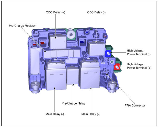
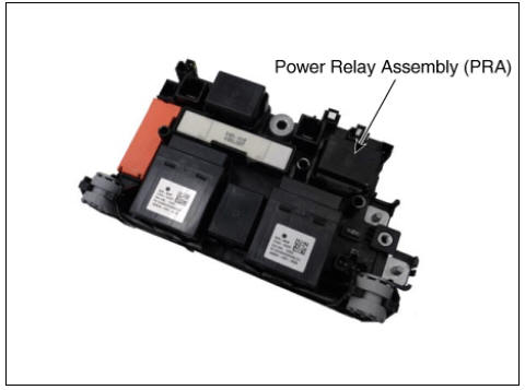
The Power Relay Assembly (PRA) consists of the positive and negative main relays, pre-charge relay, pre-charge resistor and battery current sensor. It is located inside the battery pack assembly and controls the high voltage power circuit between the high voltage battery and inverter by the control signal of BMS ECU.
PRA Operation Sequence
Power Relay Assembly (PRA) Repair procedures
Removal
Warning
- Be sure to read and follow the "General Safety Information and Caution" before doing any work related with the high voltage system. Failure to follow the safety instructions may result in serious electrical injuries.
- Be sure to read and follow the "High Voltage Shut-off Procedures" before doing any work related with the high voltage system. Failure to follow the safety instructions may result in serious electrical injuries.
- Shut off the high voltage.
(Refer to "High voltage Shut-off Procedures")
- Remove the rear seat cushion.
(Refer to Body - "Rear Seat Assembly")
- Remove the rear door scuff trim.
(Refer to Body - "Door Scuff Trim")
- Remove the inlet cooling duct.
(Refer to High Voltage Battery Cooling System - "Cooling Duct")
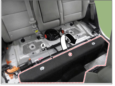
- Open the floor carpet (A) to the arrow direction.
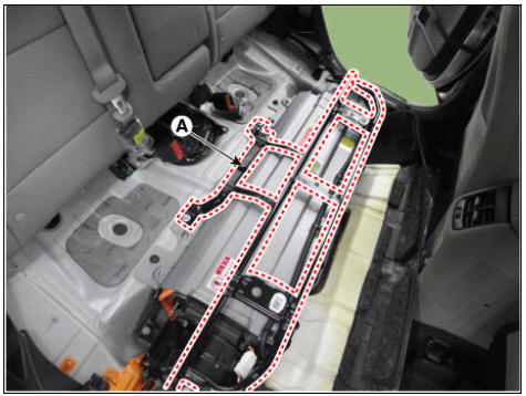
- Remove the upper frame (A) after loosening the mounting bolts and nuts.
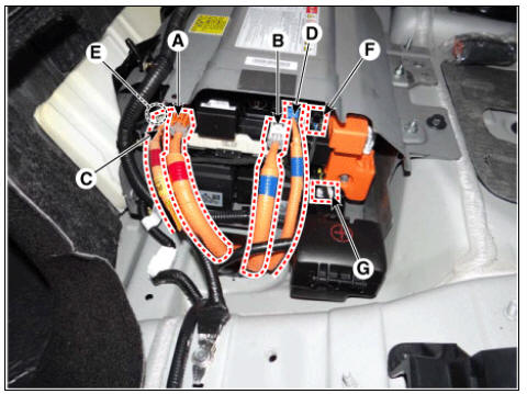
- Disconnect the connectors in the illustration below.
- Inverter power connector (+)
- Inverter power connector (-)
- OBC power connector (+)
- OBC power connector (-)
- OBC relay connector (+)
- OBC relay connector (-)
- PRA relay connector
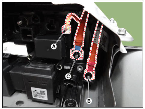
- Disconnect the battery current sensor connector (A).
- Disconnect the high voltage power cable (+) terminal (B) and (-) terminal (C).
High voltage power cable terminal tightening nut : 7.8 - 11.8 N.m (0.8 - 1.2 kgf.m, 5.8 - 8.7 lb-ft)
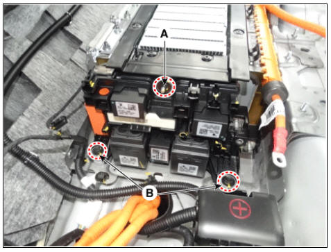
- Remove the power relay assembly (RPA) after loosening the mounting nut (A) and bolt (B).
PRA mounting nut : 7.8 - 11.8 N.m (0.8 - 1.2 kgf.m, 5.8 - 8.7 lb-ft)
Installation
Warning
- Be sure to read and follow the "General Safety Information and Caution" before doing any work related with the high voltage system. Failure to follow the safety instructions may result in serious electrical injuries.
- Be sure to read and follow the "High Voltage Shut-off Procedures" before doing any work related with the high voltage system. Failure to follow the safety instructions may result in serious electrical injuries.
- Install the power relay assembly in the reverse order of removal.
READ NEXT:
 Main High Voltage Battery Front Cover | Sub High Voltage Battery upper Cover
Removal
Warning
Be sure to read and follow the "General Safety Information and Caution" before doing any work related with the high voltage system. Failure to follow the safety instructions may result in serious electrical inj
SEE MORE:
Power tailgate
Operating the power tailgate
Operation
Press the power tailgate open/close
button inside the vehicle or with the
smart key for 1 second. The power
tailgate opens with a warning sound.
Press and hold the power tailgate
open/clos
Smart Key Diagnostic Repair procedures
Inspection
In the body electrical system, failure can be quickly diagnosed by using
the vehicle diagnostic system (KDS).
The diagnostic system (KDS) provides the following information.
(1) Self diagnosis : Checking failure and code number
Categories
- Home
- KIA Niro EV, Hybrid - Second generation - (SG2) (2021-2024) - Owner's manual
- Kia Niro - First generation - (DE) (2017-2022) - Service and Repair Manual
- Contact Us