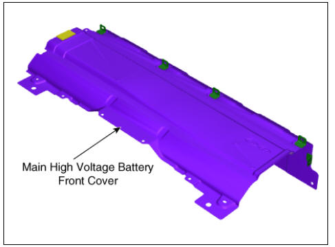
KIA Niro: Main High Voltage Battery Front Cover | Sub High Voltage Battery upper Cover
Removal
Warning
- Be sure to read and follow the "General Safety Information and Caution" before doing any work related with the high voltage system. Failure to follow the safety instructions may result in serious electrical injuries.
- Be sure to read and follow the "High Voltage Shut-off Procedures" before doing any work related with the high voltage system. Failure to follow the safety instructions may result in serious electrical injuries.
- Shut off the high voltage circuit.
(Refer to Hybrid Control System - "High Voltage Shut-off Procedures")
- Remove the rear seat cushion.
(Refer to Body - "Rear Seat Assembly")
- Remove the rear door scuff trim.
(Refer to Body - "Door Scuff Trim")
- Remove the inlet cooling duct.
(Refer to High Voltage Battery Cooling System - "Cooling Duct")
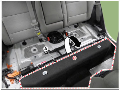
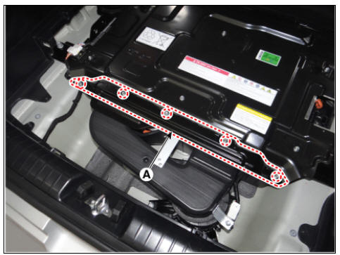
- Open the high voltage battery cushion (A) in the direction of an arrow.
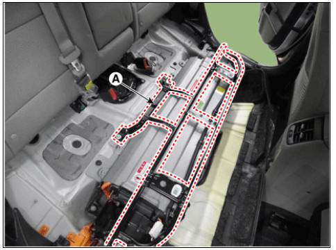
- Remove the upper frame (A) after loosening the mounting bolts and nuts.
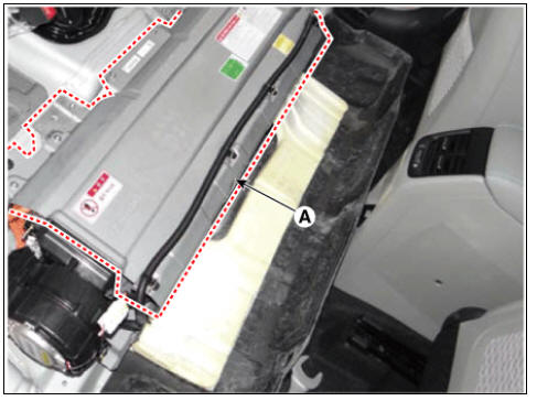
- Remove the high voltage battery front cover (A) after loosening the mounting bolts and nuts.
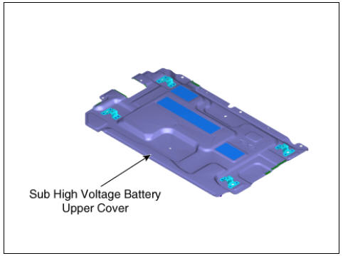
Sub High Voltage Battery upper Cover
- Turn ignition switch OFF and disconnect the negative (-) battery cable.
- Shut off the high voltage circuit.
(Refer to Hybrid Control System - "High Voltage Shut-off Procedures")
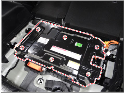
- Remove the sub high voltage battery rear cover (A) after loosening the mounting bolts.
High Voltage Battery Rear Cover mounting bolt : 7.8 - 11.8 N*m (0.8 - 1.2 kgf*m, 5.8 - 8.7 lb*ft)
- Remove the sub high voltage battery cover (A) after loosening the mounting bolts.
High Voltage Battery Cover mounting bolt : 7.8 - 11.8 N*m (0.8 - 1.2 kgf*m, 5.8 - 8.7 lb*ft)
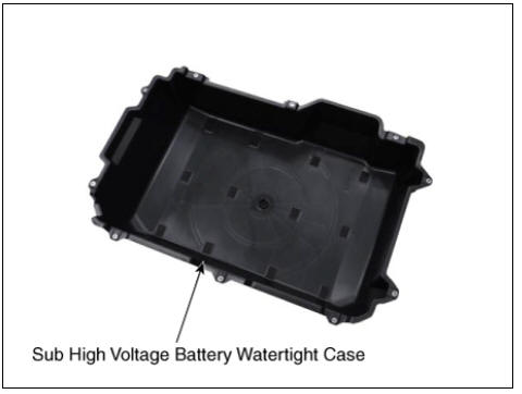
Sub High Voltage Battery Watertight Case
- Remove the sub high voltage battery pack assembly.
(Refer to Hybrid Control System - "Battery Pack Assembly")
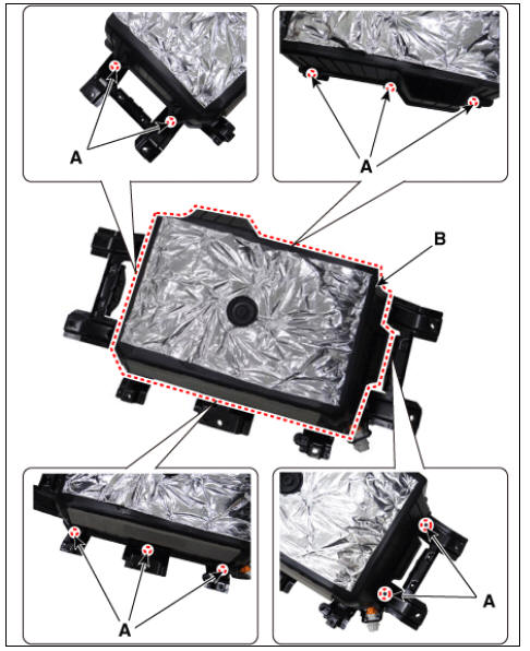
- Remove the sub high voltage battery watertight case (A) after loosening the mounting bolts.
Sub High Voltage Battery Watertight Case mounting bolt : 7.8 - 11.8 N*m (0.8 - 1.2 kgf*m, 5.8 - 8.7 lb*ft)
Installation
Warning
- Be sure to read and follow the "General Safety Information and Caution" before doing any work related with the high voltage system. Failure to follow the safety instructions may result in serious electrical injuries.
- Be sure to read and follow the "High Voltage Shut-off Procedures" before doing any work related with the high voltage system. Failure to follow the safety instructions may result in serious electrical injuries.
- Install the case in the reverse order of removal.
Description
The high voltage battery system consists of the BMS ECU (Battery Management System ECU), Power
Relay Assembly (PRA), safety plug, battery temperature sensor, and battery ambient sensor.
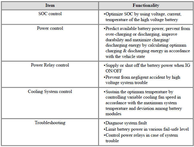
Especially the BMS ECU controls SOC (State Of Charge), power, cell balancing, cooling and
Troubleshooting of the high voltage battery system.
The PRA includes main relays (positive, negative), pre-charge relay, pre-charge resistor and battery
current sensor.
Main Functionalities
Warning
SOC (State Of Charge): available energy of the high voltage battery
READ NEXT:
 Main/ Sub High Voltage Battery
Main High Voltage Battery
Power Relay Assembly (PRA)
Cell Monitoring Unit (CMU)
Battery Temperature Sensor
Runaway Arresting Device (RAD)
Warning
Main Relays (Positive, Negative), Pre-Charge Relay, Pre-Charge
Resistor, and Battery
Safety Plug Description and operation
Description
Safety Plug is installed on the rear side of the high voltage battery and it
can mechanically shut the
high voltage circuit off when servicing the high voltage system. (i.e. High
Voltage Battery, Power
Relay Assembly, HPCU, BMS ECU
SEE MORE:
Stop Lamp Switch Repair procedures
Removal
Turn ignition switch OFF and disconnect the negative (-) battery
terminal.
Remove the crash pad lower panel.
(Refer to Body - "Crash Pad")
Remove the knee air bag.
(Refer to Restraint - "Knee Airbag(KAB) Module&q
Setting smart regeneration system (Kia Niro EV)
Smart regeneration system
The Smart Regeneration System controls
the regenerative braking automatically
according to the road gradient and
driving condition of the vehicle in front.
The system minimizes the unnecessary
operation of the brake
Categories
- Home
- KIA Niro EV, Hybrid - Second generation - (SG2) (2021-2024) - Owner's manual
- Kia Niro - First generation - (DE) (2017-2022) - Service and Repair Manual
- Contact Us