KIA Niro: Rear Lower and Upper Arm Repair procedures
Removal
- Disconnect the battery negative cable.
- Remove the wheel and tire.
Tightening torque: 107.9 - 127.5 N*m (11.0 - 13.0 kgf*m, 79.6 - 94.0 lb*ft)
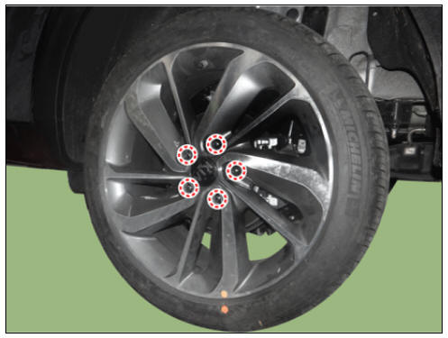
Warning
Be careful not to damage the wheel nuts when removing the wheel and tire.
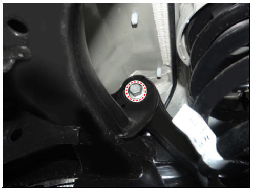
- Loosen the rear lower arm bolt (A,B), rear shock absorber bolt (C) and stabilizer link bolt (D) and then remove the rear lower arm.
Tightening torque: (A) 107.9 - 117.7 N*m (11.0 - 12.0 kgf*m, 79.6 - 86.8 lb*ft) (B) 137.3 - 156.9 N*m (14.0 - 16.0 kgf*m, 101.3 - 115.7 lb*ft) (C) 98.0 - 117.6 N*m (10.0 - 12.0 kgf*m, 72.3 - 86.7 lb*ft) (D) 19.6 - 29.4 N*m (2.0 - 3.0 kgf*m, 14.5 - 21.7 lb*ft)

Warning
Set up the transmission jack under the lower arm in order to remove the shock absorber in no-load condition.
- Install in the reverse order of removal.
- Check the wheel alignment.
(Refer to Suspension System - "Alignment")
Inspection
- Check the bushing for wear and deterioration.
- Check the rear lower arm for deformation.
- Check the coil spring and spring pad for deterioration and deformation.
- Check all bolts and nut.
Rear Upper Arm Repair procedures
Removal
- Disconnect the battery negative cable.
- Remove the wheel and tire.
Tightening torque: 107.9 - 127.5 N*m (11.0 - 13.0 kgf*m, 79.6 - 94.0 lb*ft)
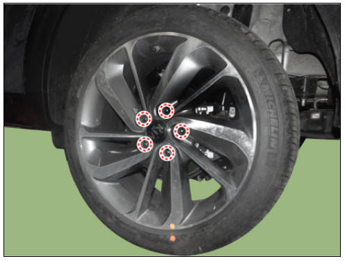
Warning
Be careful not to damage the wheel nuts when removing the wheel and tire.
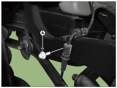
- Loosen the wheel speed sensor bracket bolt (A) from the rear upper arm.
Tightening torque: 6.8 - 10.7 N*m (0.7 - 1.1 kgf*m, 5.0 - 7.9 lb*ft)
Warning
Set up the transmission jack under the lower arm in order to remove the shock absorber in no-load condition.
- Loosen the bolt from the upper arm.
Tightening torque: 137.3 - 156.9 N*m (14.0 - 16.0 kgf*m, 101.3 - 115.7 lb*ft)
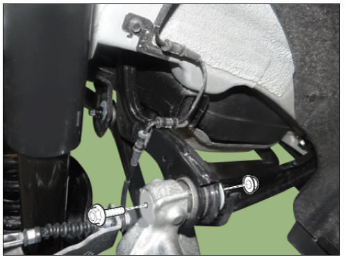
- Loosen the upper arm bolt and then remove the upper arm.
Tightening torque: 137.3 - 156.9 N*m (14.0 - 16.0 kgf*m, 101.3 - 115.7 lb*ft)
- Install in the reverse order of removal.
Inspection
- Check the bushing for wear and deterioration.
- Check all bolts and nuts.
READ NEXT:
 Rear Stabilizer Bar Repair procedures
Removal
Disconnect the battery negative cable.
Remove the wheel and tire.
Tightening torque:
107.9 - 127.5 N*m (11.0 - 13.0 kgf*m, 79.6 - 94.0 lb*ft)
Warning
Be careful not to damage the wheel nuts when removing the wheel and
tire.
Trailing Arm Repair procedures
Removal
Disconnect the battery negative cable.
Remove the wheel and tire.
Tightening torque:
107.9 - 127.5 N*m (11.0 - 13.0 kgf*m, 79.6 - 94.0 lb*ft)
Warning
Be careful not to damage the wheel nuts when removing the wheel and
tire.
SEE MORE:
Cruise Control (CC)
Cruise indicator
Set speed
Cruise Control will allow you to drive at
speeds above 30 km/h (20 mph) without
depressing the accelerator pedal.
Cruise Control operation
Setting speed
Accelerate to the desired speed,
which must be m
Climate control air filter
Replacing the climate control air filter
Operation
Open the glove box and remove the
stopper (1). With the glove box open,
remove the glove box by pushing the
both sides of it (2).
Remove the climate control air filter
cover (2
Categories
- Home
- KIA Niro EV, Hybrid - Second generation - (SG2) (2021-2024) - Owner's manual
- Kia Niro - First generation - (DE) (2017-2022) - Service and Repair Manual
- Contact Us