KIA Niro: Steering Gear box Repair procedures
Removal
- Disconnect the battery negative cable.
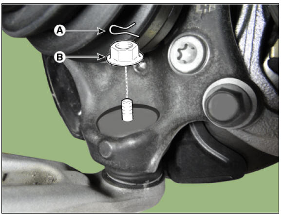
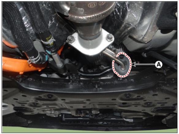
- Remove the universal bolt (A).
Tightening torque : 32.4 - 37.3 N*m (3.3 - 3.8 kgf*m, 23.9 - 27.5 lb*ft)
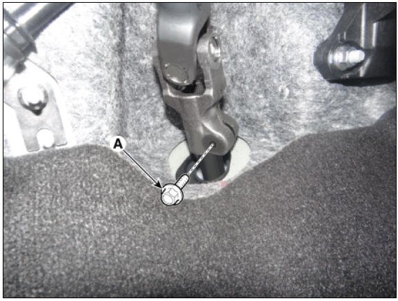
Warning
- Keep neutral range to prevent damaging the clock spring inner cable when steering the wheel.
- Do not reuse the bolt.
- Remove the wheel and tire.
Tightening torque: 107.9 - 127.5 N*m (11.0 - 13.0 kgf*m, 79.6 - 94.0 lb*ft)
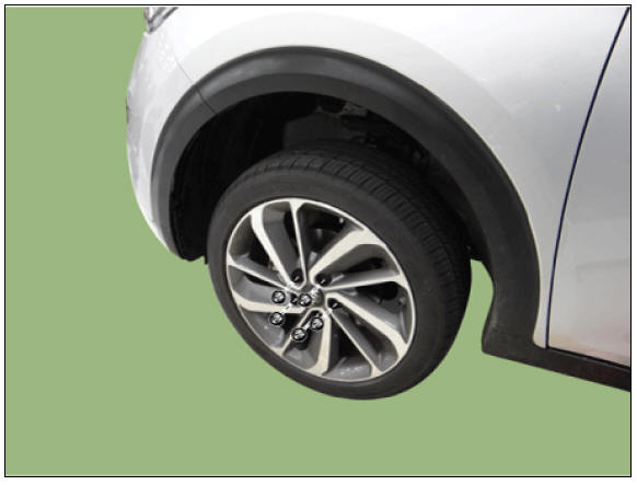
Warning
Be careful not to damage the wheel nuts when removing the wheel and tire.
- Remove the under cover.
(Refer to Engine Mechanical System - "Engine Room Under Cover")
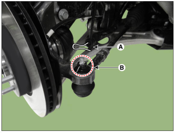
- Remove the tie rod end pin (A) and nub (B).
Tightening torque: 78.4 - 98.0 N*m (8.0 - 10.0 kgf*m, 57.8 - 72.3 lb*ft)
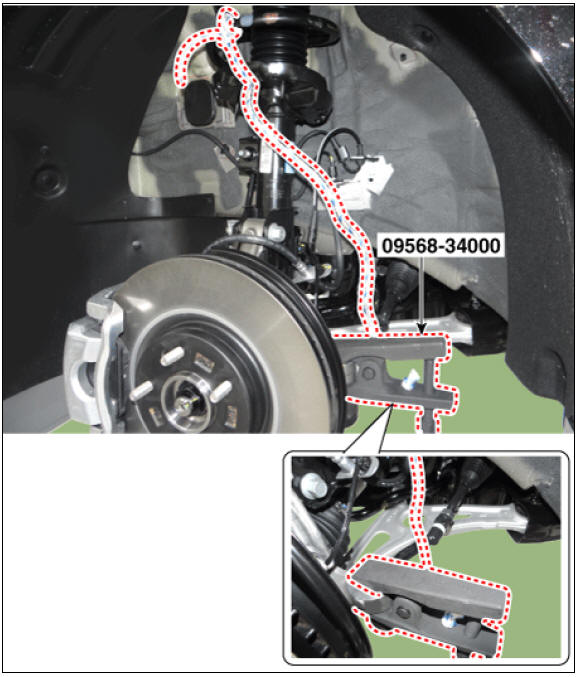
- Remove the knuckle by using the SST (09568-34000).
- Disconnect the lower arm from the knuckle by using the SST (09568-1S100).
(1) Remove the lower arm pin (A) and nut (B).
Tightening torque : 78.5 - 98.1 N*m (8.0 - 10.0 kgf*m, 57.9 - 72.3 lb*ft)
(2) Disconnect the lower arm from the knuckle by using the SST (09568-1S100).
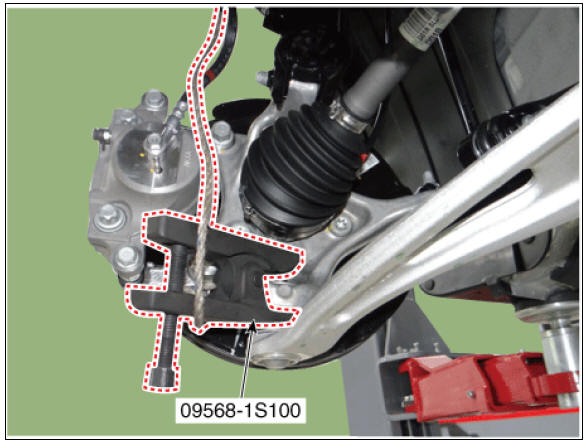
Warning
- When using SST, be sure not to damage the dust cover of lower arm ball joint.
- Keep SST tied to the car because there is a risk of injury by dropping the SST during removing the lower arm ball joint.
- The peripheral parts may be damaged when removing the lower arm ball joint with a general tool such as lever, so be sure to use SST.
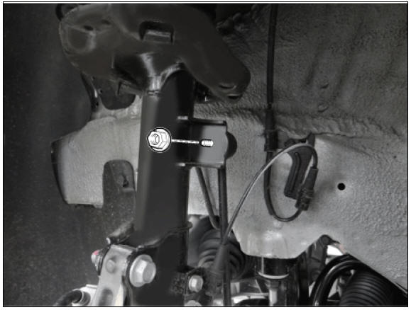
- Remove the stabilizer link nut.
Tightening torque: 98.0 - 117.6 N*m (10.0 - 12.0 kgf*m, 72.3 - 86.7 lb*ft)
- Loosen the nuts and then remove the heat protector.
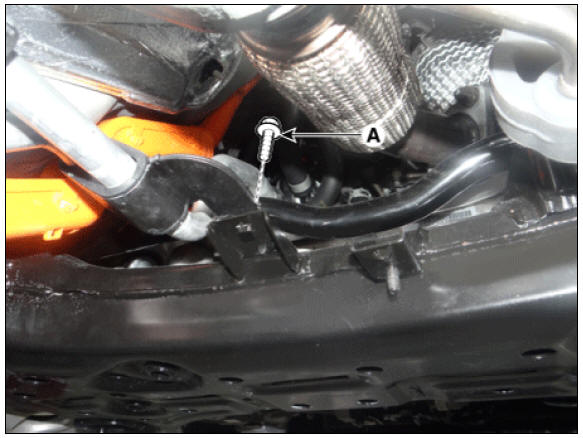
- Remove the hanger (A).
- Remove the roll rod bracket.
(Refer to Engine Mechanical System - "Engine Mounting")
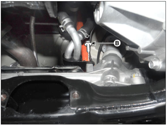
- Loosen the bolts (A) and (B) and then remove the coolant pipe.
Tightening torque: 6.8 - 10.7 N*m (0.7 - 1.1 kgf*m, 5.0 - 7.9 lb*ft)
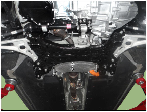
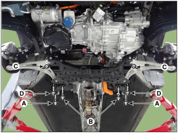
- Loosen the bolts (A,B) and nuts (C,D) and then remove the sub frame.
Tightening torque: Bolts : (A) 44.1 - 53.9 N*m (4.5 - 5.5 kgf*m, 32.5 - 39.8 lb*ft) (B) 176.5 - 196.1 N.m (18.0 - 20.0 kgf.m, 130.2 - 144.6 lb-ft) Nuts : (C) 176.5 - 196.1 N.m (18.0 - 20.0 kgf.m, 130.2 - 144.6 lb-ft) (D) 44.1 - 53.9 N*m (4.5 - 5.5 kgf*m, 32.5 - 39.8 lb*ft)
Warning
Set up the transmission jack under the subframe in order to remove the shock absorber in no-load condition .
- Loosen the bolts and then remove the gearbox heat protector.
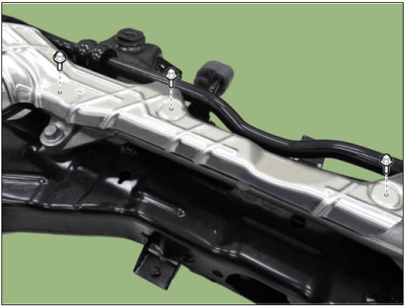
- Loosen the bolts and then remove the front stabilizer bar.
Tightening torque: 44.1 - 53.9 N*m (4.5 - 5.5 kgf*m, 32.5 - 39.8 lb*ft)
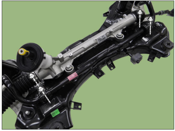
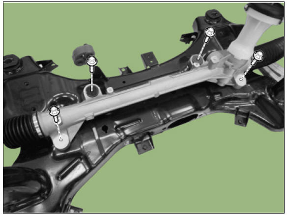
- Loosen the bolts and then remove the gear box.
Tightening torque: 88.3 - 107.9 - 127.5 N*m (9.0 - 11.0 kgf*m, 65.1 - 79.6 lb*ft)
- Install in the reverse order of removal.
- Check the wheel alignment.
(Refer to Suspension System - "Alignment")
Replacement
Warning
- Do not disassembly the steering gear box.
- If the steering gear box is disassembled, its quality (noise / cleanliness / functions) cannot be guaranteed.
Interchangeable parts
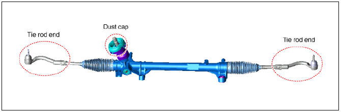
Tie rod end
- Remove the tie rod end after loosening the nut.
Tightening torque : 49.0 - 53.9 N*m (5.0 - 5.5 kgf*m, 36.2 - 39.8 lb*ft)
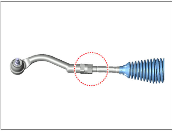
Warning
Before removing the tie rod end, take the measurement or mark with paint the length of the thread.
- Replace the tie rod end.
- Check the alignment.
(Refer to Suspension System - "Alignment")
Dust cap
- Remove the dust cap cover.
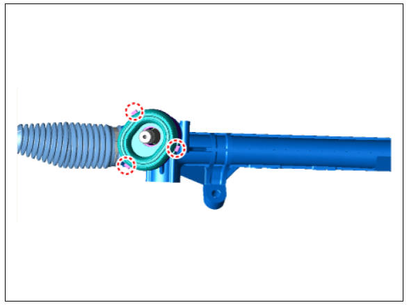
- Remove the dust cap.
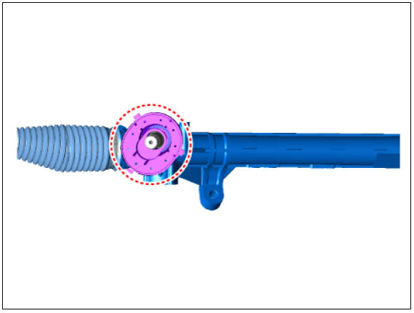
- Install in the reverse order of removal.
READ NEXT:
 Steering Wheel / Repair Procedures
Steering Wheel / Components And Components Location
Bezel
Lower cover
Damper
Steering wheel
Remote control switch
Wire ring
Steering Wheel / Repair Procedures
Removal
Disconnect the battery negative cable.
Turn the steerin
Heated Steering wheel
Description
When manually selected, the heated steering wheel system improves the thermal
comfort of the driver
by heating the steering wheel.
Specifications
System Circuit Diagram
Terminal Function
Inspection
NTC characteris
SEE MORE:
Auto defogging for automatic climate control
Auto defogging for automatic climate control
Operation
For Europe
Air conditioning will turn ON at
recirculation mode.
Mode will change to defrost to
direct airflow to the windshield.
Fan speed will increase.
Except Europe
Ai
Replacing glove box lamp (Bulb type)
Operation
Using a flat-blade screwdriver, gently
pry the lamp assembly from interior.
Remove the cover from the lamp
assembly.
Remove the bulb by pulling it straight
out.
Install a new bulb in the socket.
Install the cover
Categories
- Home
- KIA Niro EV, Hybrid - Second generation - (SG2) (2021-2024) - Owner's manual
- Kia Niro - First generation - (DE) (2017-2022) - Service and Repair Manual
- Contact Us