KIA Niro: Brake Actuation Unit Repair procedures
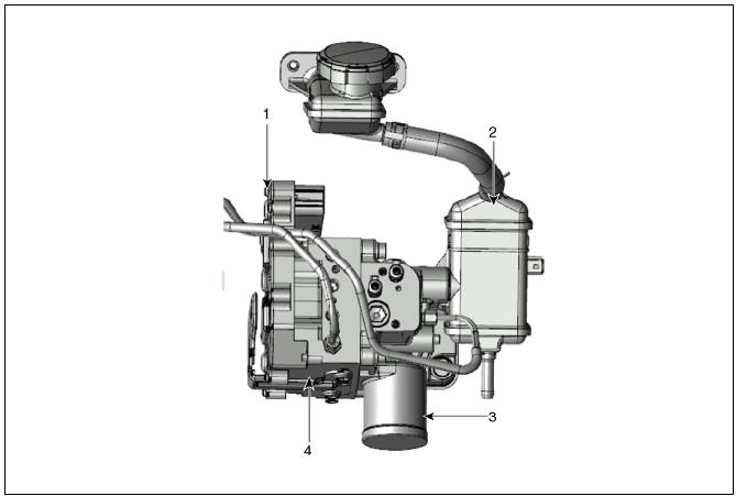
Brake Actuation Unit Components and components location
Warning
IBAU(Intergrated Brake Actuation Unit) must not be disassembled.
- Integrated Brake Actuation Unit (IBAU) ECU
- Reservoir
- Pedal Simulator
- Integrated Brake Actuation Unit (IBAU)
Brake Actuation Unit Repair procedures
Removal
Warning
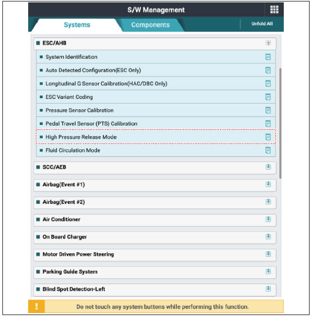
The following section describes how to diagnose faults using a diagnostic instrument.
1) Connect self-diagnosis connector (16pins) located under the driver side crash pad to self-diagnosis device, and then turn the self-diagnosis device after key is ON.
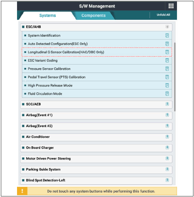
2) Select the "vehicle model" and "ESC/AHB" on KDS vehicle selection screen.
3) Select the "High Pressure Release Mode" on KDS screen, then select OK.
4) Proceed with the test according to the screen instructions.
- Turn ignition switch OFF and disconnect the negative (-) battery terminal.
- Disconnect the ECM & TCM bracket.
(Refer to Engine Control System - "Engine Control Module (ECM)")
- Remove the air cleaner assembly.
(Refer to Engine Mechanical System - "Air Cleaner")
- Remove the brake fluid from the master cylinder reservoir with a syringe.
Warning
Do not spill brake fluid on the vehicle as it may damage the paint. If brake fluid comes in contact with the paint, wash off immediately with water.
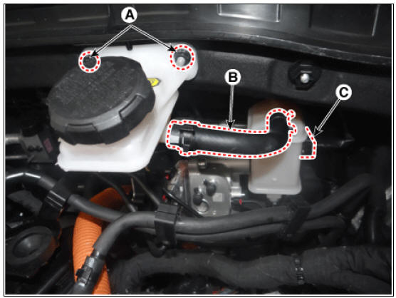
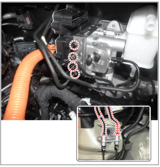
- Remove the nuts (A), hose (B), brake fluid level sensor connector (C).
Tightening torque: 6.8 - 10.7 N*m (0.7 - 1.1 kgf*m, 5.0 - 7.9 lb*ft)
- Disconnect the integrated brake actuation unit (IBAU) connector (A) and brake tube (B).
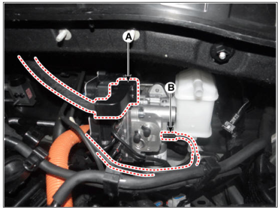
- Loosen the flare nuts (A) from the integrated brake actuation unit (IBAU) and then remove the brake tube.
Tightening torque: 12.7 - 16.7 N*m (1.3 - 1.7 kgf*m, 9.4 - 12.3 lb*ft)
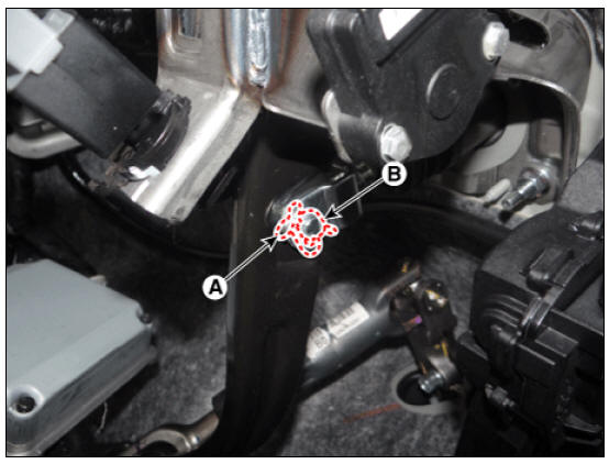
- Remove the snap pin (A) and clebis pin (B).
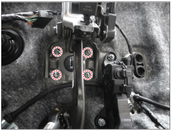
- Loosen the brake pedal nuts.
Tightening torque : 16.7 - 25.5 N*m (1.7 - 2.6 kgf*m, 12.3 - 18.8 lb*ft)
Installation
- Installation is the reverse of removal.
- Check the brake pedal operation.
- After filling the brake fluid in the reservoir, perform the air bleed.
(Refer to the Brake system - "Brake Bleeding Procedure")
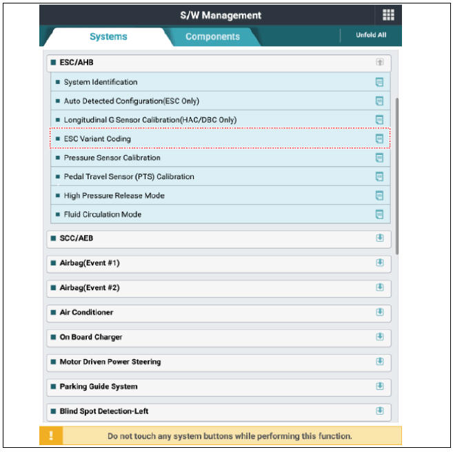
- Conduct the variant coding.
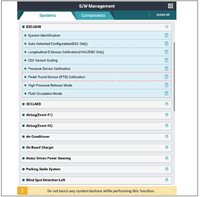
- Conduct the pedal traval sensor (PTS) calibration.
- Conduct the longitidinal G sensor clibration. (HAC/DBC Only)
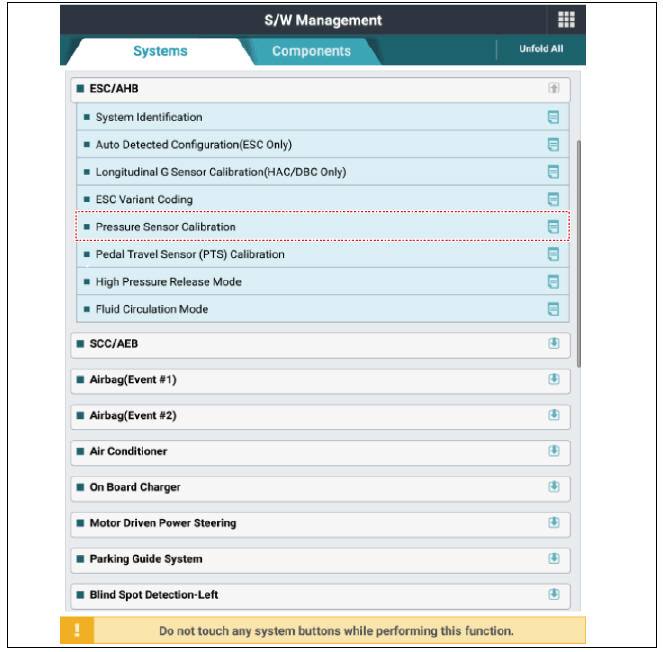
- Conduct the pressure sensor calibration.
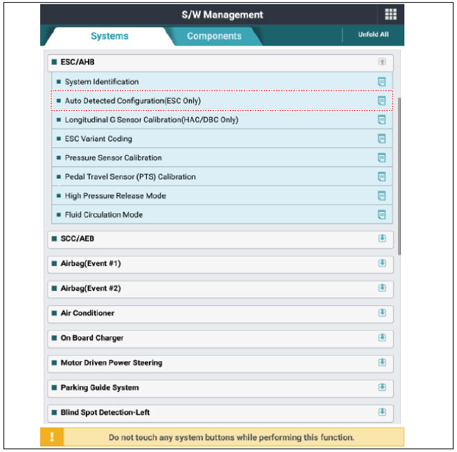
- Conduct the auto detected configuration reset the if necessary.
Diagnosis by using diagnostic device
The following section describes how to diagnose faults using a diagnostic instrument.
- Connect self-diagnosis connector (16pins) located under the driver side crash pad to self-diagnosis device, and then turn the selfdiagnosis device after key is ON.
- Select the "vehicle model" and "ESC/AHB" on KDS vehicle selection screen.
- Proceed with the test according to the screen instructions.
Longitudinal G Sensor Calibration(HAC/DBC Only)
Pressure Sensor Calibration
Pedal Travel Sensor (PTS) Calibration
Auto Detected Configuration Reset(ESP(ESC) Only)
ESC Variant Coding
READ NEXT:
 Pressure Source Unit Repair procedures
Pressure Source Unit Components and components location
Warning
PSU (Presser Source Unit) must not be disassembled.
Pressure Source Unit (PSU)
Pressure Source Unit (PSU) connector
Motor
Filler adapter
Bracket
Accumulator
Remova
Brake Line
Brake Line Components and components location
Removal
Disconnect the brake fluid level switch connector, and remove the
reservoir cap.
Remove the brake fluid from the master cylinder reservoir with a
syringe.
Warning
Do not spill
Brake Pedal
Brake pedal member assembly
Stop lamp switch
Brake pedal arm
Brake pedal pad
Brake pedal stroke sensor
Removal
Turn ignition switch OFF and disconnect the negative (-) battery
terminal.
Remove the crash pad lower panel.
(
SEE MORE:
If an accident
occurs
WARNING
For your safety, do not touch the high
voltage cables, connectors and package
modules. High voltage components
are orange in color.
Exposed cables or wires may be visible
inside or outside of the vehicle.
Never touch the wires
Rear View Monitor operation
Parking/View button
Press the Parking/View button (1) to turn
on Rear View Monitor.
Press the button again to turn off the
function.
Rear view function
Operating conditions
Rear View Monitor will turn on when the
following condition
Categories
- Home
- KIA Niro EV, Hybrid - Second generation - (SG2) (2021-2024) - Owner's manual
- Kia Niro - First generation - (DE) (2017-2022) - Service and Repair Manual
- Contact Us