KIA Niro: Pressure Source Unit Repair procedures
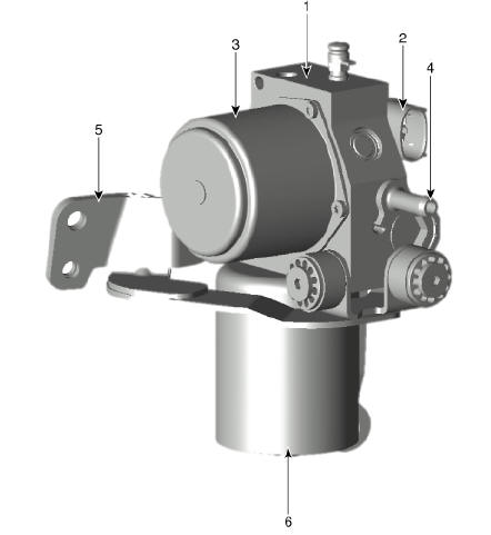
Pressure Source Unit Components and components location
Warning
PSU (Presser Source Unit) must not be disassembled.
- Pressure Source Unit (PSU)
- Pressure Source Unit (PSU) connector
- Motor
- Filler adapter
- Bracket
- Accumulator
Removal
Warning
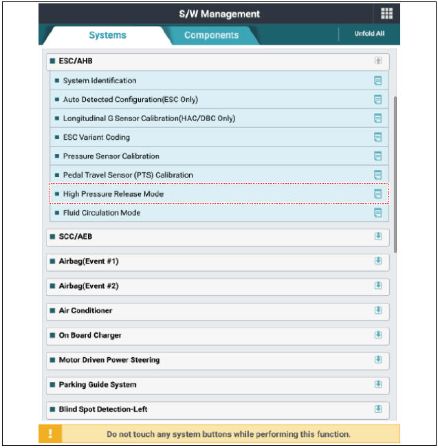
The following section describes how to diagnose faults using a diagnostic instrument.
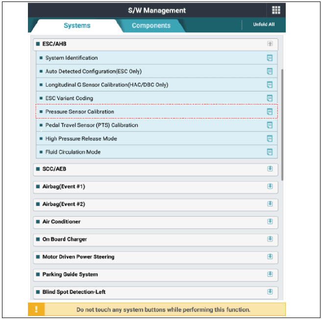
1) Connect self-diagnosis connector (16pins) located under the driver side crash pad to self-diagnosis device, and then turn the self-diagnosis device after key is ON.
2) Select the "vehicle model" and "ESC/AHB" on KDS vehicle selection screen.
3) Select the "High Pressure Release Mode" on KDS screen, then select OK.
4) Proceed with the test according to the screen instructions.
- Turn ignition switch OFF and disconnect the negative (-) battery terminal.
- Remove the air cleaner assembly.
(Refer to Engine Mechanical System - "Air Cleaner")
- Remove the brake fluid from the master cylinder reservoir with a syringe.
Warning
Do not spill brake fluid on the vehicle as it may damage the paint. If brake fluid comes in contact with the paint, wash off immediately with water.
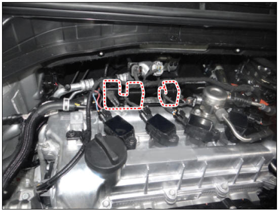
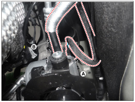
- Remove the connector and wire ring bracket.
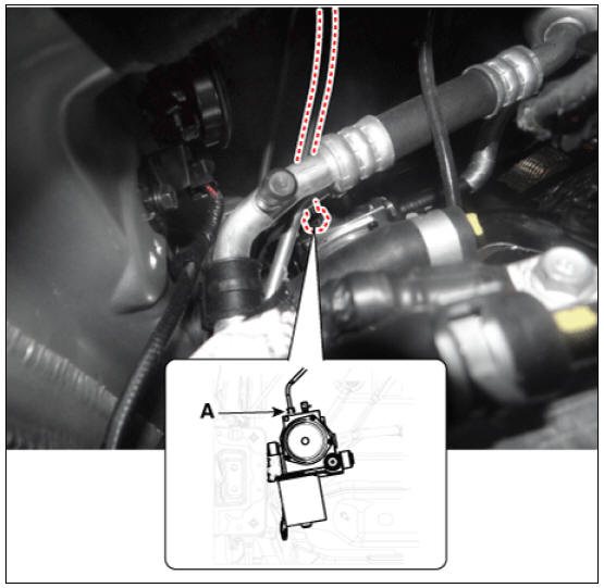
- Loosen the pressure source unit (PSU) flare nut (A) and then remove the tube.
Tightening torque: 12.7 - 16.7 N*m (1.3 - 1.7 kgf*m, 9.4 - 12.3 lb*ft)
- Disconnect the pressure source unit (PSU) connector (A) and hose (B).
- Remove the sub frame.
(Refer to Suspension System - "Sub Frame")
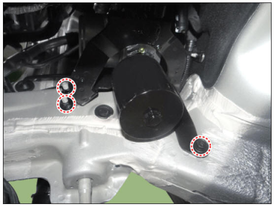
- Loosen the nuts and bolt and then remove the pressure source (PSU).
Tightening torque: 19.6 - 29.4 N*m (2.0 - 3.0 kgf*m, 14.5 - 21.7 lb*ft)
Installation
- Installation is the reverse of removal.
- Check the brake pedal operation.
- After filling the brake fluid in the reservoir, perform the air bleed.
(Refer to the Brake system - "Brake Bleeding Procedure")
- Conduct the pedal traval sensor (PTS) calibration.
(Refer to the Brake System - "Brake Pedal")
- Conduct the pressure sensor calibration.
Diagnostic Procedure Using a Diagnostic Instrument
The following section describes how to diagnose faults using a diagnostic instrument.
- Connect self-diagnosis connector (16pins) located under the driver side crash pad to self
- Select the "vehicle model" and "ESC/AHB" on KDS vehicle selection screen.
- Proceed with the test according to the screen instructions.
Pressure Sensor Calibration
Pedal Travel Sensor (PTS) Calibration

READ NEXT:
 Brake Line
Brake Line Components and components location
Removal
Disconnect the brake fluid level switch connector, and remove the
reservoir cap.
Remove the brake fluid from the master cylinder reservoir with a
syringe.
Warning
Do not spill
Brake Pedal
Brake pedal member assembly
Stop lamp switch
Brake pedal arm
Brake pedal pad
Brake pedal stroke sensor
Removal
Turn ignition switch OFF and disconnect the negative (-) battery
terminal.
Remove the crash pad lower panel.
(
Front Disc Brake
Front Disc Brake Components and components location
Bleed screw
Caliper body
Pad inner shim
Brake pad
Pad return spring
Caliper carrier
Pad retainer
Removal
Remove the wheel & tire.
Remove the caliper hose bracket bol
SEE MORE:
Main Fuse Inspection | Checking for Welding in the High Voltage Main Relay
Turn the ignition switch OFF and disconnect the auxiliary 12V battery negative (-) terminal.
Shut off the high voltage.
(Refer to Hybrid Control System - "High voltage Shut-off Procedures")
Remove the center tra
Hybrid Power Control Unit (HPCU)/ Repair procedures
Warning
Be sure to read and follow the "General Safety Information and
Caution" before doing any work related with the high voltage
system. Failure to follow the safety instructions may result in serious
electrical injuries.
B
Categories
- Home
- KIA Niro EV, Hybrid - Second generation - (SG2) (2021-2024) - Owner's manual
- Kia Niro - First generation - (DE) (2017-2022) - Service and Repair Manual
- Contact Us