KIA Niro: Compressor oil Repair procedures | Refrigerant Line
Air Conditioning System / Components And Components Location
Engine Room
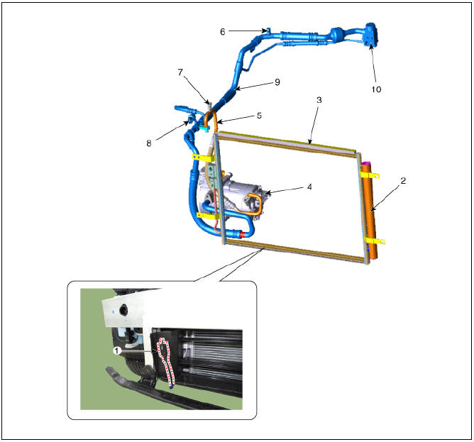
- Ambient Temperature Sensor
- Receiver-drier
- Condenser
- Electric A/C Compressor
- Discharge hose
- The service port (Low pressure)
- The service port (High pressure)
- A/C Pressure Transducer (APT)
- Suction & Liquid tube assembly
- Expansion valve
Interior
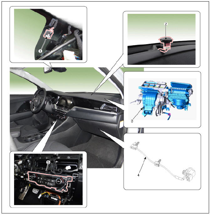
- Auto Defogging sensor
- Photo sensor
- Heater & blower unit
- Evaporator Temperature Sensor
- Heater & A/C Control Unit
Compressor oil Repair procedures
Oil Specification
The oil used to lubricate the compressor circulates with the refrigerant.
Whenever replacing any component of the system or a large amount of gas leakage occurs, add oil to maintain the original amount of oil.
Total volume of oil in system POE OIL: 130 +- 10 g (4.58 +- 0.35 oz)
Oil Return Operation
There is close affinity between the oil and refrigerant.
During normal operation, part of the oil recirculates with the refrigerant in the system. When checking the amount of oil in the system, or replacing any component of the system, the compressor must run in advance for oil return operation. The procedure is as follows:
- Open all the doors and engine hood.
- Start the engine and air conditioning switch to "ON" and set the blower motor control knob at its highest position.
- Stop the engine.
Refrigerant Line

- Suction & Liquid tube assembly
- Discharge hose
Replacement
- If a compressor is available, the air conditioner is operated for a few minutes in the engine idle state and then the engine is stopped.
- Disconnect the negative (-) battery terminal.
- Recover the refrigerant with a recovery/charging station.
- Remove the engine cover.
(Refer to Engine Mechanical System - "Engine Cover")
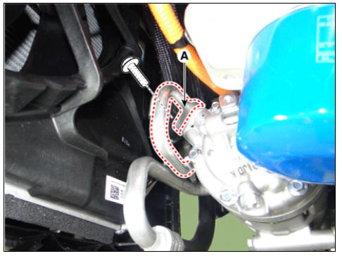
- Remove the bolts and the expansion valve (A) from the evaporator core.
Tightening torque : 7.8 - 11.8 N*m (0.8 - 1.2 kgf*m, 5.8 - 8.7 lb*ft)
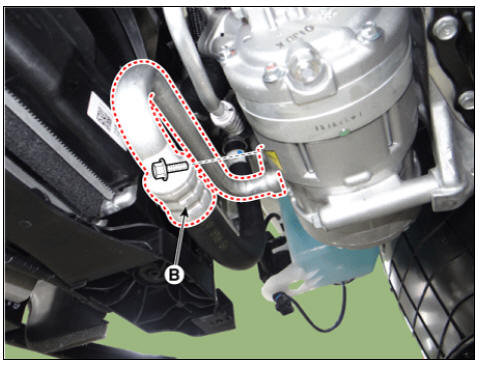
- Remove the 2 nuts, and then disconnect the discharge line (A) and liquid line (B) from the condenser.
Tightening torque : 7.8 - 11.8 N*m (0.8 - 1.2 kgf*m, 5.8 - 8.7 lb*ft)
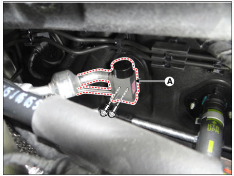
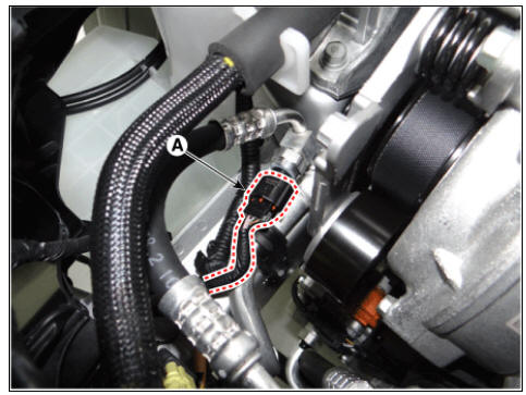
- Press the lock pin and separate the APT sensor connector (A).
- Remove the engine room under cover.
(Refer to Engine Mechanical System - "Engine Room Under Cover")
- Remove the engine mounting braket.
(Refer to Engine Mechanical System - "Engine Mounting")
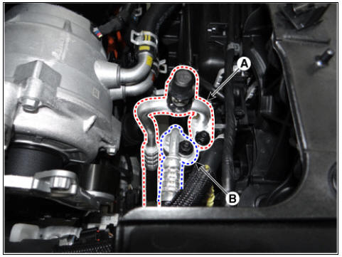
- Remove the nuts, then disconnect the suction line (A) and discharge line (B) from the compressor.
Tightening torque : 7.8 - 11.8 N*m (0.8 - 1.2 kgf*m, 5.8 - 8.7 lb*ft)
Warning
Plug or cap the lines immediately after disconnecting them to avoid moisture and dust contamination.
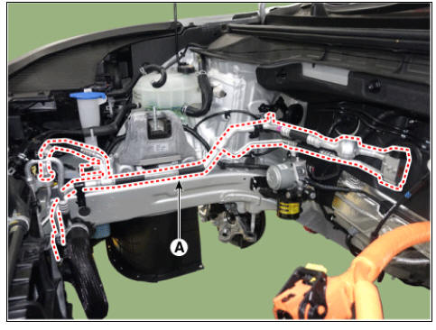
- Loosen the mounting bolts and remove the front suction & liquid pipe assembly (A).
Tightening torque : 7.8 - 11.8 N*m (0.8 - 1.2 kgf*m, 5.8 - 8.7 lb*ft)
Warning
- Plug or cap the lines immediately after disconnecting them to avoid moisture and dust contamination.
- Tighten the bolt or nut joint to the specified torque.
- Using a gas leak detector, check for refrigerant leakage.
- Evacuate air in the refrigeration system and charge system with refrigerant.
Specified amount R-134a, R-1234yf : 550 +- 25g (19.4 +- 0.88oz.)
Compressor Repair procedures
Compressor Components and components location
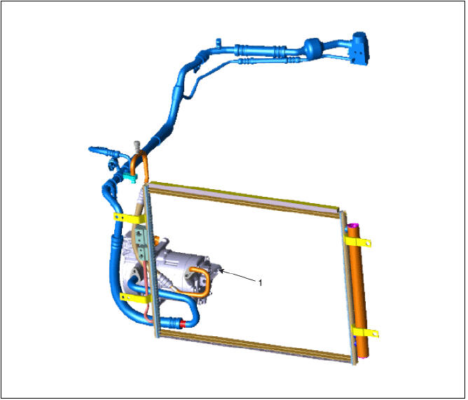
- Electric A/C Compressor
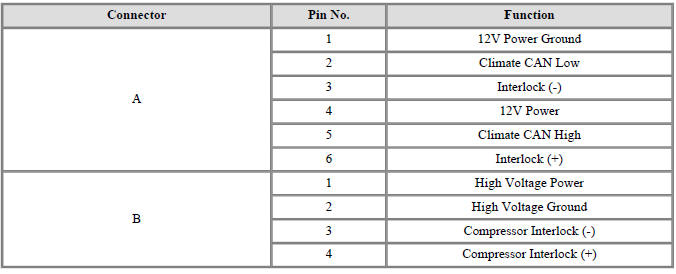
Compressor Schematic diagrams
Connector Pin
Connector Pin Function
READ NEXT:
 Electric A/C Compressor
Electric A/C Compressor body inside inspection
Electric compressor body inside check procedure.
1) Remove the low-pressure pipe from the electric compressor.
2) Check if the copper wire and white thread inside of the compressor was
contamin
Inverter kit / Body kit
Remove the battery (-) cable.
Disconnect the high voltage circuit. (Refer to Generals)
Use the recovery/reproduction/charging device to recover the coolant.
Warning
When removing the connector between the vehicle and the
compressor,
SEE MORE:
Front Wheel Speed Sensor
Front Wheel Speed Sensor Components and components location
Front wheel speed sensor
Front wheel speed sensor cable
Front Wheel Speed Sensor Repair procedures
Removal
Remove the tire.
Tightening torque:
107.9 - 127.5 N*m (11.0 -
Emission Control System
Components Location
PCV Valve
Canister
Purge Control Solenoid Valve (PCSV)
Fuel Tank Pressure Sensor (FTPS)
Fuel Level Sensor (FLS)
Fuel tank air Filter
Catalytic converter (WCC)
Gasoline Particulate Filter (GPF)
PCV Valve
Categories
- Home
- KIA Niro EV, Hybrid - Second generation - (SG2) (2021-2024) - Owner's manual
- Kia Niro - First generation - (DE) (2017-2022) - Service and Repair Manual
- Contact Us