KIA Niro: Hybrid Drive Motor Assembly Components and components location, Repair procedures
Component
location!
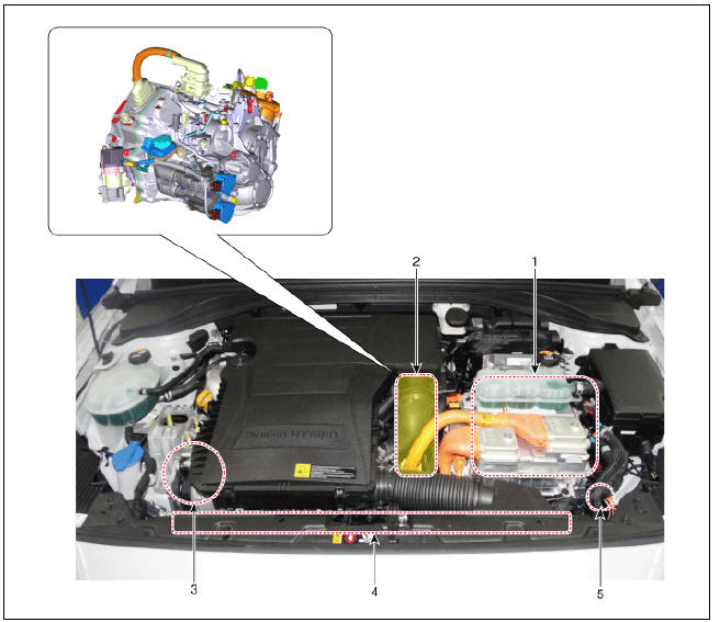
- HPCU (Hybrid Power Control Unit) (LDC+MCU+HCU+Reservoir)
- Hybrid drive motor
- Hybrid starter generator (HSG)
- Electrical radiator
- Electric water pump (EWP)
Components
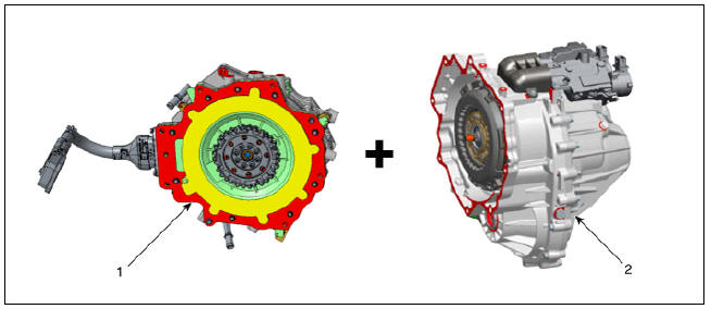
- Hybrid motor assembly
- Double clutch transmission (DCT)
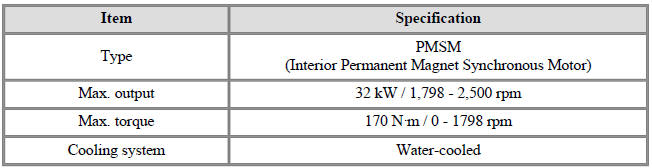
Specification
Hybrid Drive Motor Assembly Repair procedures
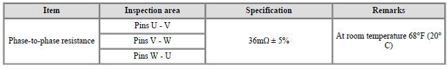
Inspection
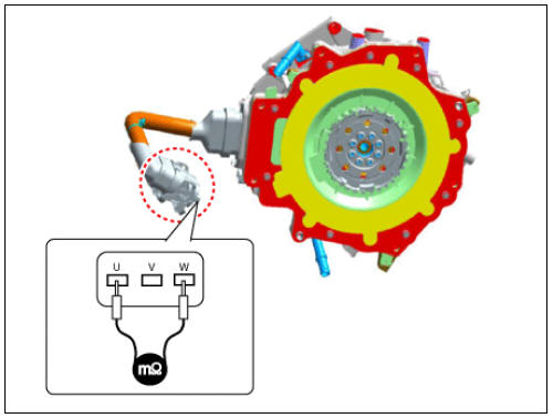
- Using mΩ tester, measure the line-to-line resistance.
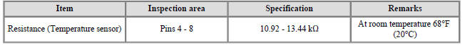
- Inspect the temperature sensor resistance.
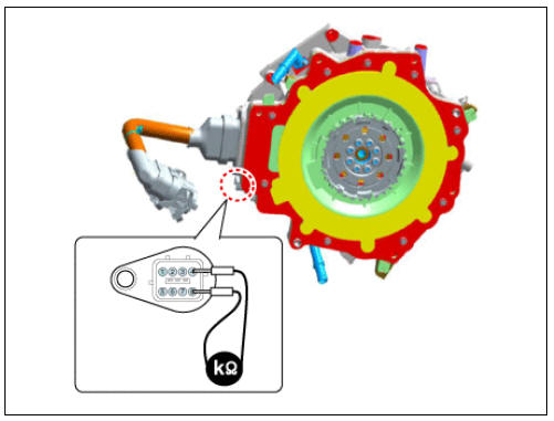
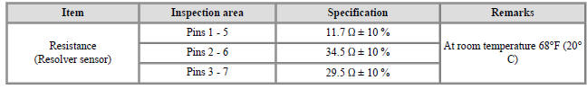
- Inspect the resolver sensor resistance.
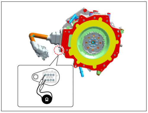
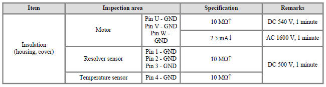
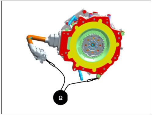
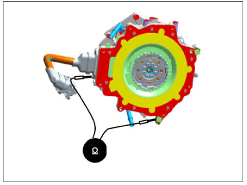
- Inspect the insulation resistance.
Removal
- Remove the hybrid drive motor & dual clutch transmission assembly from the vehicle.
(Refer to DCT System - "DCT(Double Clutch Transmission) System")
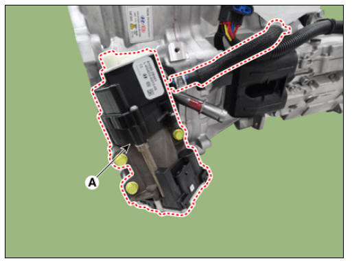
- Remove the engine clutch actuator (A).
Tightening torque : 21.6 - 26.5 N*m (2.2 - 2.7 kgf*m, 15.9 - 19.5 lb*ft)
- Remove the concentric slave cylinder.
(Refer to Clutch System - "Concentric Slave Cylinder Assembly")
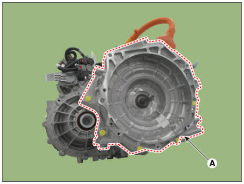
- Remove the hybrid drive motor (A) by loosening the bolts.
Tightening torque : 42.2 - 53.9 N*m (4.3 - 5.5 kgf*m, 31.1 - 39.8 lb*ft)
Installation
- Install in the reverse order of removal.
Warning
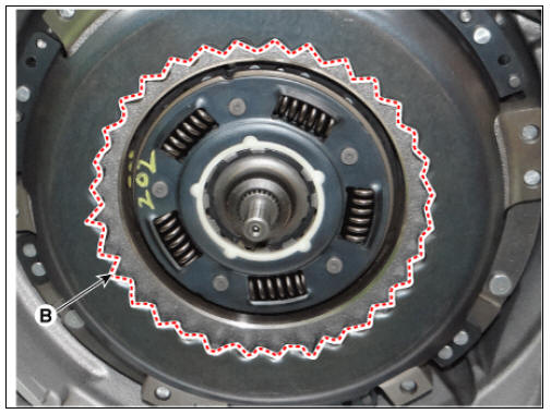
1) Check the pilot bearing (B) and motor side connector (A) on the side of engine for any dents, damages and deformations before installing the DCT. 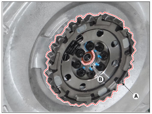
2) Align the motor side connector spline (A) with the dual clutch spline (B). 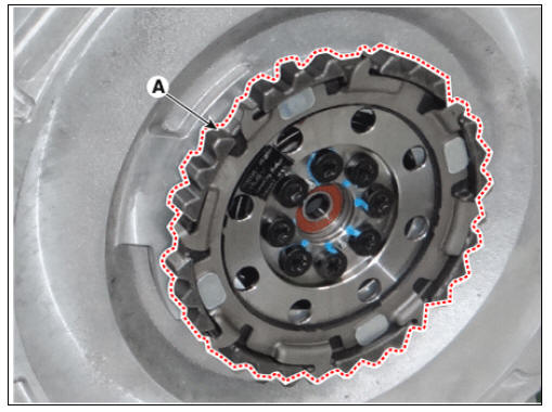
3) Insert the input shaft (A) into the pilot bearing (B) and then assemble the DCT to the bushing on the motor side. 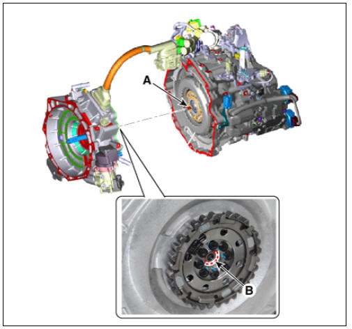
4) After mounting the DCT to the engine by pushing the DCT, tighten the mounting bolts making sure that there is no gap (less than 2 mm) between the clutch housing and the engine block.
(If the bolt is tightened while there is a gap, then the spline of motor side connector or clutch will be damaged or broken.)
- Perform the procedure below after installing.
(1) Refill the hybrid motor cooling system with coolant and then perform the air bleeding using the KDS.
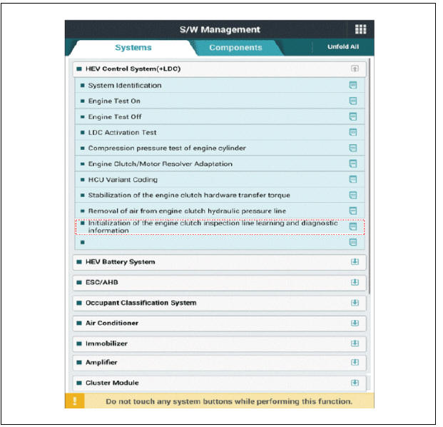
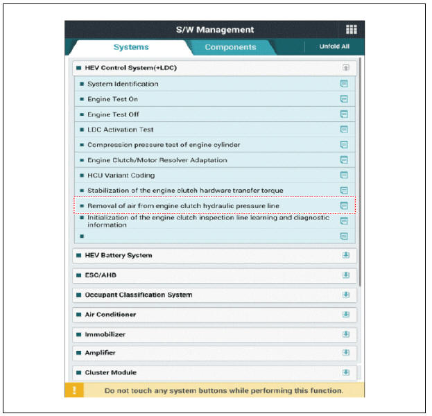
(Refer to Hybrid Motor System - "Coolant") (2) Perform learning of the engine clutch inspection line and initialization of diagnostic information using the KDS.
(3) Refill the engine clutch reservoir with brake fluid and then perform the air bleeding using the KDS.
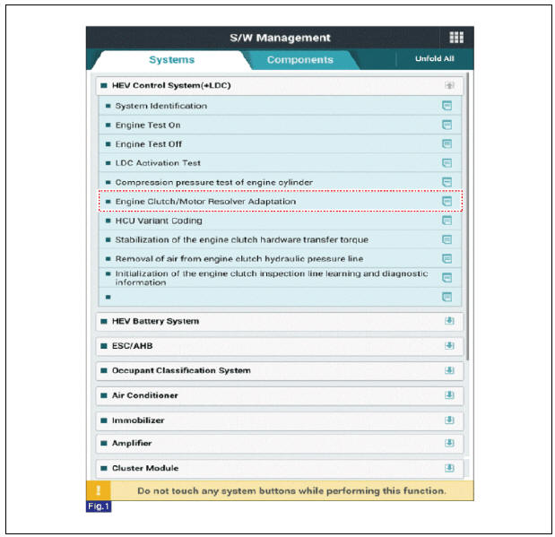
(4) Perform the engine clutch / motor resolver adaptation using the KDS.
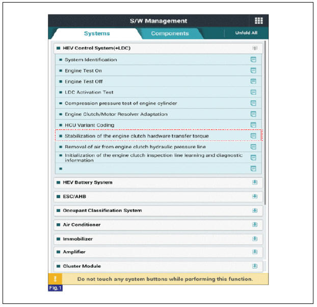
(5) Stabilize the engine clutch hardware transfer torque using the KDS.
READ NEXT:
 Hybrid Starter Generator(HSG)
Component location
HPCU (Hybrid Power Control Unit)
(LDC+MCU+HCU+Reservoir)
Hybrid drive motor
Hybrid starter generator (HSG)
Electrical radiator
Electric water pump (EWP)
Specification
Inspection
Inspect the line to lin
Hybrid Motor Control System
Description
The Hybrid Power Control Unit (HPCU), composed of various components, is
the core device among the Power Electronics
devices that acts as the brain.
It comprises of the Hybrid Control Unit (HCU), an inverter Motor Control
Un
SEE MORE:
Connecting Rod
Check the connecting rod side clearance.
Using a feeler gauge, measure the end play while moving the connecting rod
back and forth.
If out-of-tolerance, install a new connecting rod.
If still out-of-tolerance, replace the crankshaft.
Armed stage
The system provides an
audible alarm and the hazard
warning lights blink if
triggered. The system is
operated in 3 stages.
Armed stage
Operation
Lock the doors by pressing the lock
button on the key or door handle.
The hazard warning li
Categories
- Home
- KIA Niro EV, Hybrid - Second generation - (SG2) (2021-2024) - Owner's manual
- Kia Niro - First generation - (DE) (2017-2022) - Service and Repair Manual
- Contact Us