KIA Niro: DC Fuse
Component Location
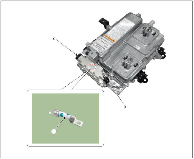
- DC Fuse
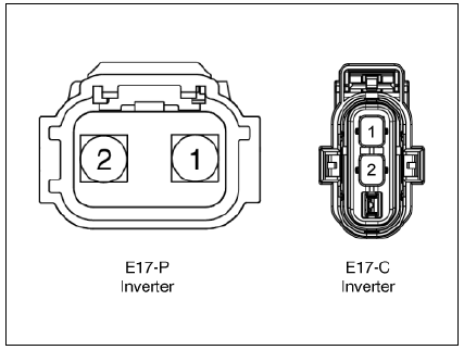
- Inverter Connector (↔ Power Relay Assembly (PRA))
- Inverter Connector (↔ Electric A/C compressor)
Component Location
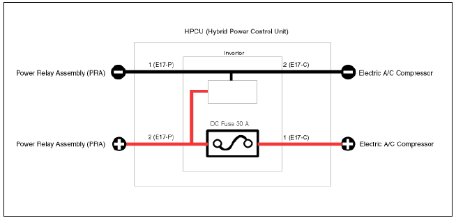
Harness Connector
DC Fuse Repair procedures
Removal
Warning
- Be sure to read and follow the "General Safety Information and Caution" before doing any work related with the high voltage system. Failure to follow the safety instructions may result in serious electrical injuries.
- Be sure to read and follow the "High Voltage Shut-off
Procedures" before doing any work related with the high voltage system.
Failure to follow the safety instructions may result in serious electrical injuries.
- Shut off the high voltage circuit.
(Refer to Hybrid Control System - "High Voltage Shut-off Procedure")
- Remove the air cleaner assembly and air duct.
(Refer to Engine Mechanical System - "Air Cleaner")
- Remove the ECM & TCM bracket assembly.
(Refer to Engine Control/Fuel System - "Engine Control Module")
- Drain the coolant of hybrid motor cooling system.
(Refer to Hybrid Motor Cooling System - "Coolant")
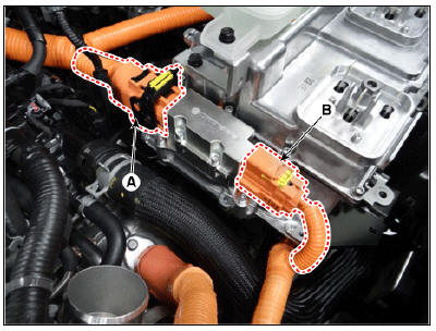
- Disconnect the motor power cable connector (A) and HSG power cable connector (B) after loosening the mounting bolts.
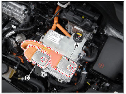
- Disconnect the power cable (A) and inverter power cable (B) from the HPCU.
Warning
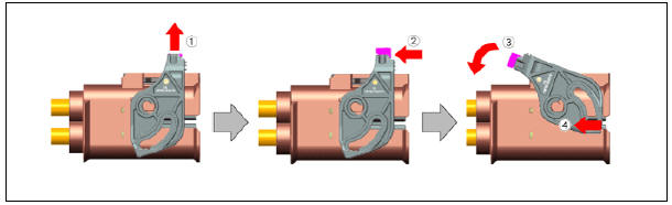
Remove the inverter power cale in the follwing order.
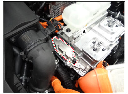
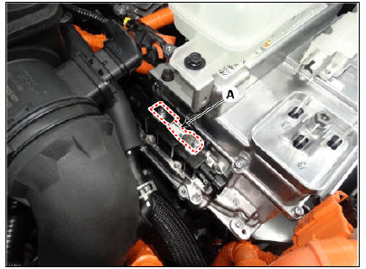
- Remove the DC fuse cover (A) after loosening the mounting bolt.
DC fuse cover installation bolt: 4.9 - 6.9 N.m (0.5 - 0.7 kgf.m, 3.6 - 5.1 lb-ft)
- Remove the DC fuse seal cover (A).
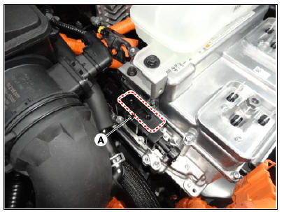
- Remove the DC fuse (A) from the HPCU after loosening the mounting bolt.
DC fuse installation bolt : 9.3 - 10.4 N.m (0.95 - 1.06 kgf.m, 6.9 - 7.7 lb-ft)
Installation
Warning
- Be sure to read and follow the "General Safety Information and Caution" before doing any work related with the high voltage system. Failure to follow the safety instructions may result in serious electrical injuries.
- Be sure to read and follow the "High Voltage Shut-off
Procedures" before doing any work related with the high voltage system.
Failure to follow the safety instructions may result in serious electrical injuries.
- Install the DC fuse in the reverse order of removal.
Battery Pack Assembly
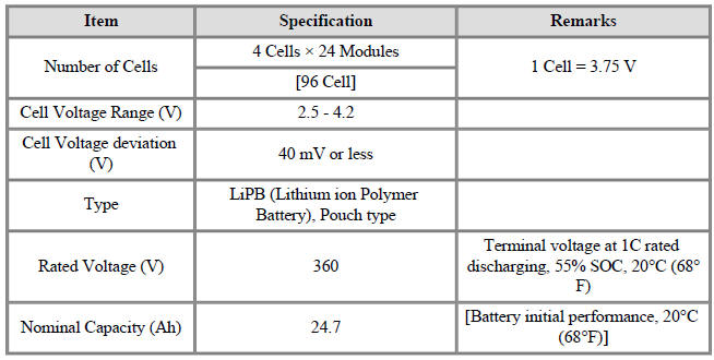
General Specification
Warning
Main high voltage battery pack assembly (180V) + Sub high voltage battery pack assembly (180V)
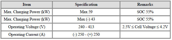
Operating Specification
Power Relay Assembly (PRA)

READ NEXT:
 High Voltage Battery System / Components And Components Location
Description
The High Voltage Battery System provides the hybrid drive motor, HSG, and
electric A/C compressor
with electric energy and also reserves the electric energy generated during
regeneration braking.It
consists of the battery pack asse
High Voltage Battery System / Repair Procedures
Removal
Warning
Be sure to read and follow the "General Safety Information and
Caution" before doing any work related with the high
voltage system. Failure to follow the safety instructions may result in
serious electrical inju
SEE MORE:
Resolver Sensor Repair procedures | Motor Temperature Sensor Repair procedures
Inspection
Hybrid Drive Motor
Inspect the resolver sensor resistance.
If the resolver sensor needs to be replaced, replace the hybrid drive motor assembly.
(Refer to Hybrid Motor Assembly - "Hybrid Drive M
Drive Belt Tensioner Repair procedures
Removal and
Installation
Remove the drive belt.
(Refer to Drive Belt System - "Drive Belt")
Remove the mechanical tensioner (A).
Tightening torque :
18.6 - 23.5 N*m (1.9 - 2.4 kgf*m, 13.7 - 17.4 lb*ft)
Remove the hydr
Categories
- Home
- KIA Niro EV, Hybrid - Second generation - (SG2) (2021-2024) - Owner's manual
- Kia Niro - First generation - (DE) (2017-2022) - Service and Repair Manual
- Contact Us