KIA Niro: High Voltage Battery System / Components And Components Location
Kia Niro - First generation - (DE) (2017-2022) - Service and Repair Manual / Hybrid Control System / High Voltage Battery System / High Voltage Battery System / Components And Components Location
Description
The High Voltage Battery System provides the hybrid drive motor, HSG, and
electric A/C compressor
with electric energy and also reserves the electric energy generated during
regeneration braking.It
consists of the battery pack assembly, BMS ECU, power relay assembly, case,
control wiring, cooling
fan, and cooling ducts.
This battery is a Lithium ion Polymer Battery (LiPB) and has 96 cells (4 Cells x
24 Modules). The
voltage of each cell is 3.75V DC, so the rated voltage of this battery pack is
360V DC.
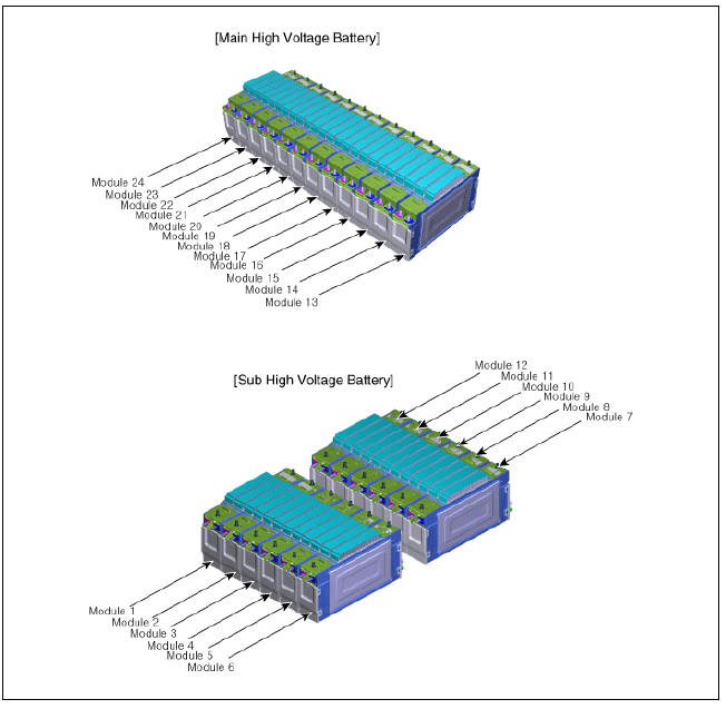
High Voltage Battery System / Components And Components Location
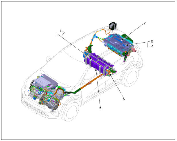
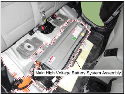
- Main High Voltage Battery System Assembly
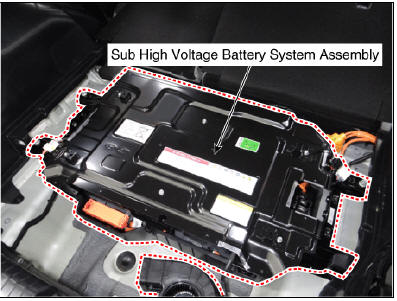
- Sub High Voltage Battery System Assembly
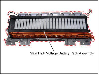
- Main High Voltage Battery Pack Assembly
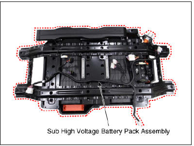
- Sub High Voltage Battery Pack Assembly
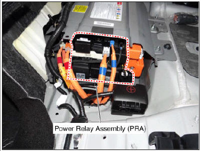
- Power Relay Assembly (PRA)
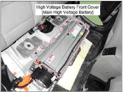
- High Voltage Battery Front Cover (Main High Voltage Battery)
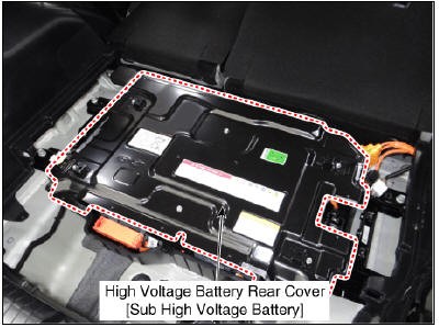
- High Voltage Battery Rear Cover (Sub High Voltage Battery)
High Voltage Battery System / Repair Procedures
- Main High Voltage Battery System Assembly
- Sub High Voltage Battery System Assembly
- Main High Voltage Battery Pack Assembly
- Sub High Voltage Battery Pack Assembly
- Power Relay Assembly (PRA)
- High Voltage Battery Front Cover (Main High Voltage Battery)
- High Voltage Battery Rear Cover (Sub High Voltage Battery)
Schematic Diagram
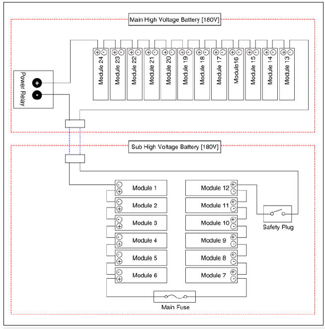
Module Number
READ NEXT:
 High Voltage Battery System / Repair Procedures
Removal
Warning
Be sure to read and follow the "General Safety Information and
Caution" before doing any work related with the high
voltage system. Failure to follow the safety instructions may result in
serious electrical inju
Sub Battery Pack Assembly
Warning
Be sure to read and follow the "General Safety Information and
Caution" before doing any work related with the high
voltage system. Failure to follow the safety instructions may result in
serious electrical injuries.
Be sure to
Battery Pack Assembly Repair procedures
Warning
Be sure to read and follow the "General Safety Information and
Caution" before doing any work related with the high
voltage system. Failure to follow the safety instructions may result in
serious electrical injuries.
Be sure to
SEE MORE:
Low Voltage DC/DC Converter (LDC)
Component Location
Low Voltage DC/DC Converter (LDC) (HPCU)
Low Voltage DC/DC Converter (LDC) power output
terminal (+) (DC 12V)
Low Voltage DC/DC Converter (LDC) ground terminal (-)
Schematic Diagram
Low Voltage DC/DC Converter
Input speed sensor | Inhibitor Switch
Component Location
Input speed sensor
Specification
Input Speed Sensor Description and operation
Description
The input shaft speed sensor is important in that it detects the input shaft RPM and sends this information to the
Categories
- Home
- KIA Niro EV, Hybrid - Second generation - (SG2) (2021-2024) - Owner's manual
- Kia Niro - First generation - (DE) (2017-2022) - Service and Repair Manual
- Contact Us