KIA Niro: DCT Control Module (TCM), Repair procedures
Kia Niro - First generation - (DE) (2017-2022) - Service and Repair Manual / DCT(Dual Clutch Transmission) System / Dual Clutch Transmission Control System / DCT Control Module (TCM), Repair procedures
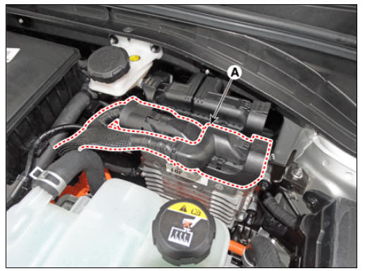
Conponent Location
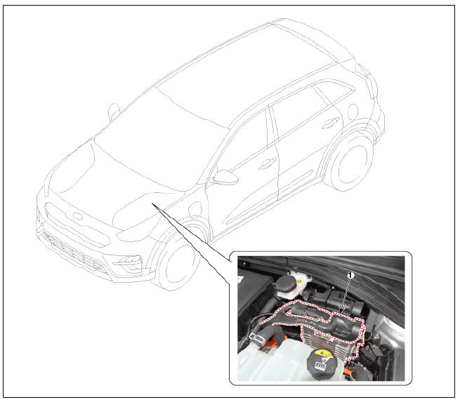
- DCT Control Module (TCM)
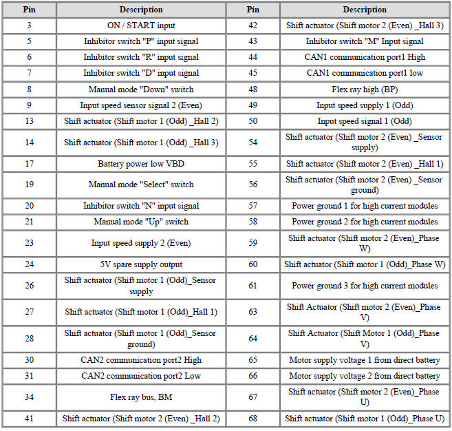
TCM Connector
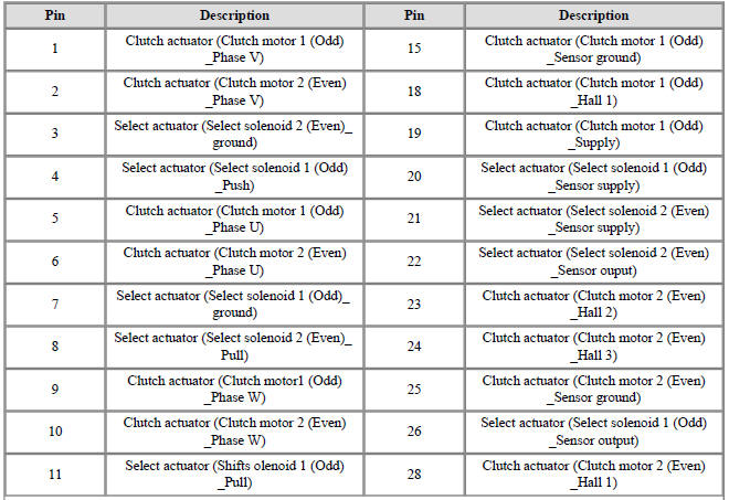
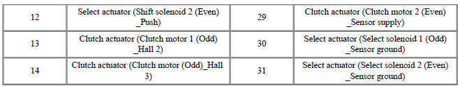
TCM Terminal Function
Connector (A)
Connector (B)
Circuit Diagram
Inspection
- TCM ground circuit test : Measure the resistance between TCM and chassis ground. (Inspect the terminal connected to the chassis ground with the back of harness connector as the inspection point of TCM side.)
Specification : Below 1Ω
- TCM connector test : Disconnect the TCM connector and visually check the ground terminals on TCM side and harness side for bent pins or poor contact pressure.
- If problem is not found in Steps 1 and 2, the TCM could be faulty.
If so, replace the TCM with a new one, and then check the vehicle again. If the vehicle operates normally then the problem was likely with the TCM.
- Reinspection of original TCM : Install the original TCM (probably broken) into a known-good vehicle and check the vehicle. If the problem occurs again, replace the original TCM with a new one.
If the problem does not recur, this is an intermittent problem and other part may be faulty.
DCT Control Module (TCM) Repair procedures
Removal
- Disconnect the battery negative (-) cable.
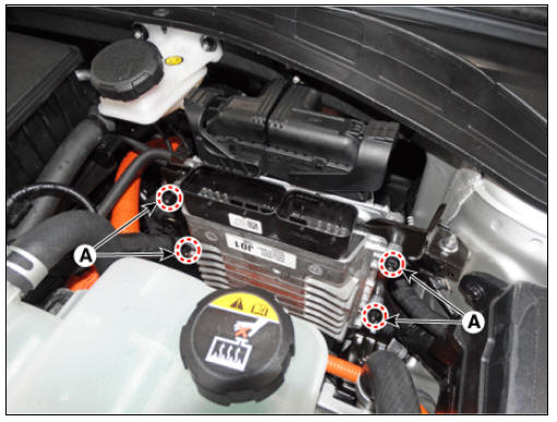
- Disconnect the TCM connector (A).
- Remove the TCM after loosening the nuts (A).
Tightening torque : 9.8 - 11.8 N*m (1.0 - 1.2 kgf*m, 7.2 - 8.7 lb*ft)
Installaion
- Install in the reverse order of removal.
Warning
Perform the clutch touch point learning procedure using the KDS after replacing TCM. 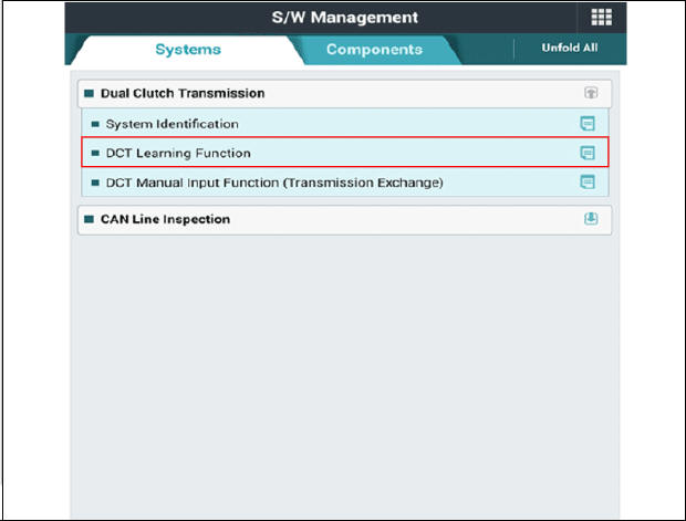
READ NEXT:
 Clutch Actuator Assembly
Components
Fork cover
Clutch actuator assembly
Extension connector
Motor 1 (Odd)
Motor 2 (Even)
Specifications
Description
The clutch actuator uses signals from the Transmission Control Module (TCM)
to control the clutch.
Clutch Actuator Motor
Remove the under cover.
(Refer to Engine Mechanical System - "Engine Room Under Cover")
Remove the front wheel guard (LH).
(Refer to Body - "Front Wheel Guard")
Disconect the clutch actuator connector (A).
Motor
SEE MORE:
DCT(Dual Clutch Transmission) System
Specifications
Double Clutch Transmission
Warning
Refer to oil replacement procedure due to drained oil quantity
can be more or less than oil
capacity.
If genuine DCT oil that is developed for best performance is
not using, it may
Parking Brake Cable Repair procedures
Removal
Turn ignition switch OFF and disconnect the negative (-) battery
terminal.
Remove the crash pad lower panel.
(Refer to Body - "Crash Pad")
Remove the knee air bag.
(Refer to Restraint - "Knee Airbag(KAB) Module&q
Categories
- Home
- KIA Niro EV, Hybrid - Second generation - (SG2) (2021-2024) - Owner's manual
- Kia Niro - First generation - (DE) (2017-2022) - Service and Repair Manual
- Contact Us