KIA Niro: Electric parking brake control
Kia Niro - First generation - (DE) (2017-2022) - Service and Repair Manual / Brake System / Electric parking brake control
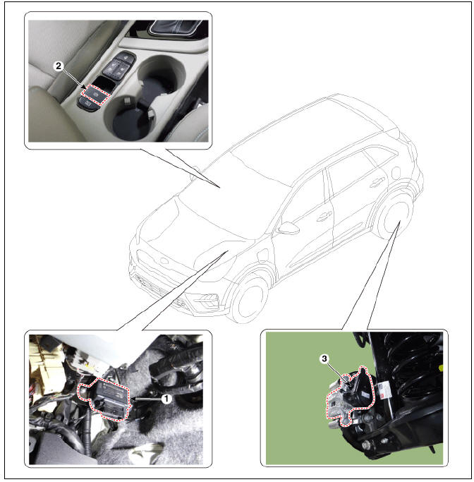
- Electric parking brake control module
- EPB switch
- EPB actuator
Removal and Installation
EPB Actuator
- Turn ignition switch off and disconnect the battery (-) cable from the battery.
- Remove the rear caliper.
(Refer to Brake System - "Rear Disc Brake")
- Install in the reverse order of removal.
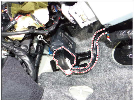
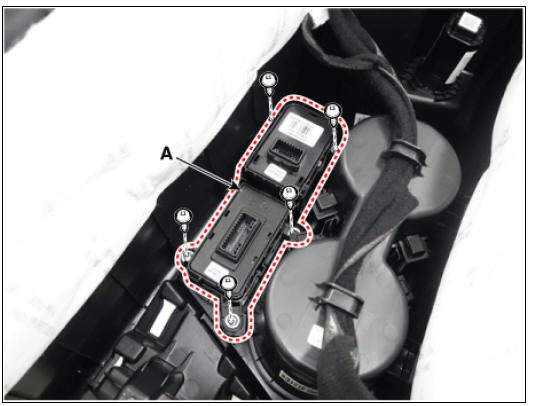
EPB Control Module
- Turn ignition switch off and disconnect the battery (-) cable from the battery.
- Disconnect the EPB control module connector (A).
- Remove the EPB control module (A) after loosening the nuts.
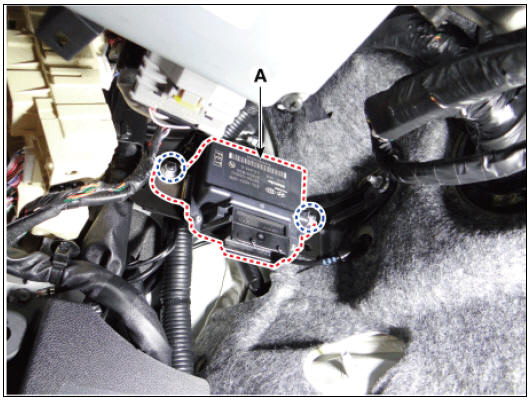
- Install in the reverse order of removal.
Removal and Installation
- Turn ignition switch off and disconnect the battery (-) cable from the battery.
- Remove the floor console assembly.
(Refer to Body - "Floor Console Assembly")
- Disconnect the console upper cover switch connectors (A).
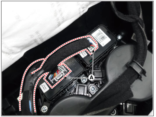
- Remove the console upper cover switch (A) after loosening the mounting screws.
- Install in the reverse order of removal.
READ NEXT:
 ESP(Electronic Stability Program) System / Description And Operation
ESP(Electronic Stability Program) System / Components And Components
Location
Pressure Source Unit (PSU)
Integrated Brake Actuation Unit (IBAU)
Front wheel speed sensor
Rear wheel speed sensor
Description
Electronic Stability Prog
Front Wheel Speed Sensor
Front Wheel Speed Sensor Components and components location
Front wheel speed sensor
Front wheel speed sensor cable
Front Wheel Speed Sensor Repair procedures
Removal
Remove the tire.
Tightening torque:
107.9 - 127.5 N*m (11.0 -
SEE MORE:
Collision warning
A: Collision warning!
While Smart Cruise Control is operating,
when the collision risk with the vehicle
ahead is high, the warning message will
appear on the cluster, and an audible
warning will sound to warn the driver.
Always have your
Front Door / Repair Procedures
Front Door / Components And Components Location
Front door trim
Front door module & panel
Front door belt outside weatherstrip
Front door side weatherstrip
Front door body side weatherstrip
Front door window glass run
Front do
Categories
- Home
- KIA Niro EV, Hybrid - Second generation - (SG2) (2021-2024) - Owner's manual
- Kia Niro - First generation - (DE) (2017-2022) - Service and Repair Manual
- Contact Us