KIA Niro: ESP(Electronic Stability Program) System / Description And Operation
ESP(Electronic Stability Program) System / Components And Components Location
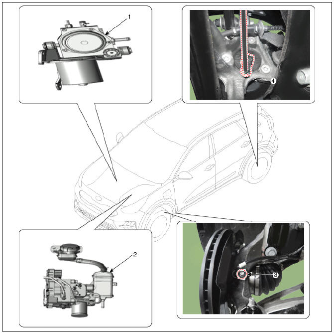
- Pressure Source Unit (PSU)
- Integrated Brake Actuation Unit (IBAU)
- Front wheel speed sensor
- Rear wheel speed sensor
Description
Electronic Stability Program (ESP) recognizes critical driving conditions, such as panic reactions in dangerous situations, and stabilizes the vehicle by wheel-individual braking and engine control intervention.
ESP adds a further function known as Active Yaw Control (AYC) to the ABS, TCS, EBD and ESP functions. Whereas the ABS/TCS function controls wheel slip during braking and acceleration and, thus, mainly intervenes in the longitudinal dynamics of the vehicle, active yaw control stabilizes the vehicle about its vertical axis.
This is achieved by wheel individual brake intervention and adaptation of the momentary engine torque with no need for any action to be taken by the driver.
ESP essentially consists of three assemblies : the sensors, the electronic control unit and the actuators.
The stability control feature works under all driving and operating conditions. Under certain driving conditions, the ABS/TCS function can be activated simultaneously with the ESP function in response to a command by the driver.
In the event of a failure of the stability control function, the basic safety function, ABS, is still maintained.
Description of ESP Control
ESP system includes ABS/EBD, TCS and AYC function.
ABS/EBD function : The ECU changes the active sensor signal (current shift) coming from the four wheel sensors to the square wave. By using the input of above signals, the ECU calculates the vehicle speed and the acceleration & deceleration of the four wheels. And, the ECU judges whether the ABS/EBD should be actuated or not.
TCS function prevents the wheel slip of drive direction by adding the brake pressure and engine torque reduction via CAN communication. TCS function uses the wheel speed sensor signal to determine the wheel slip as far as ABS function.
AYC function prevents unstable maneuver of the vehicle. To determine the vehicle maneuver, AYC function uses the maneuver sensor signals(Yaw Rate Sensor, Lateral Acceleration Sensor, Steering Wheel Angle Sensor).
If vehicle maneuver is unstable (Over Steer or Under Steer), AYC function applies the brake pressure on certain wheel, and send engine torque reduction signal by CAN.
After the key-on, the ECU continually diagnoses the system failure. (self-diagnosis)If the system failure is detected, the ECU informs driver of the system failure through the BRAKE/ABS/ESP warning lamp. (fail-safe warning)
Input and Output Diagram
ESP Operation Mode
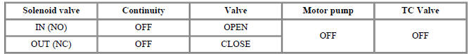
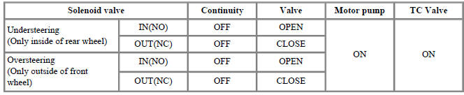
ESP Hydraulic System Diagram
- ESP Non-operation : Normal braking.
- ESP operation
ABS Warning Lamp module
The active ABS warning lamp module indicates the self-test and failure status of the ABS. The ABS warning lamp shall be on:
- During the initialization phase after IGN ON. (continuously 3 seconds).
- In the event of inhibition of ABS functions by failure.
- During diagnostic mode.
- When the ECU Connector is seperated from ECU.
- Cluster lamp is ON when communication is impossible with CAN module.
EBD/Parking Brake Warning Lamp Module
The active EBD warning lamp module indicates the self-test and failure status of the EBD. However, in case the Parking Brake Switch is turned on, the EBD warning lamp is always turned on regardless of EBD functions. The EBD warning lamp shallbe on:
- During the initialization phase after IGN ON. (continuously 3 seconds).
- When the Parking Brake Switch is ON or brake fluid level is low.
- When the EBD function is out of order .
- During diagnostic mode.
- When the ECU Connector is seperated from ECU.
- Cluster lamp is ON when communication is impossible with CAN module.
ESP Function/Warning Lamp (ESP system)
The ESP function/warning lamp indicates the self-test and failure status of the ESP.
The ESP function/warning lamp is turned on under the following conditions :
- During the initialization phase after IGN ON. (continuously 3 seconds).
- When the ESP function is inhibited by system failure.
- When the ESP control is operating. (Blinking - 2Hz)
- During diagnostic mode.(Except standard mode)
- Cluster lamp is ON when communication is impossible with CAN module.
ESP Off Lamp (ESP system)
The ESP Off lamp indicates the self-test and operating status of the ESP.
The ESP Off lamp operates under the following conditions :
- During the initialization mode after IGN ON. (continuously 3 seconds).
- ESP Off lamp is On when driver input the ESP Off switch.
ESP On/Off Switch (ESP system)
The ESP On/Off Switch shall be used to toggle the ESP function between On/Off states based upon driver input.
The On/Off switch shall be a normally open, momentary contact switch.Closed contacts switch the circuit to ignition.
Initial status of the ESP function is on and switch toggle the state.
ESP(Electronic Stability Program) System - Troubleshooting
Failure Diagnosis
- In principle, ESP and TCS controls are prohibited in case of ABS failure.
- When ESP or TCS fails, only the failed system control is prohibited.
- However, when the solenoid valve relay should be turned off in case of ESP failure, refer to the ABS fail-safe.
- Information on ABS fail-safe is identical to the fail-safe in systems where ESP is not installed.
Memory of Fail Code
- It keeps the code as far as the backup lamp power is connected. (O)
- It keeps the code as far as the HCU power is on. (X)
Failure Checkup
- Initial checkup is performed immediately after the HECU power on.
- Valve relay checkup is performed immediately after the IG2 ON.
- It executes the checkup all the time while the IG2 power is on.
Countermeasures in Fail
- Turn the system down and perform the following actions and wait for HECU power OFF.
- Turn the valve relay off.
- Stop the control during the operation and do not execute any until the normal condition recovers.
Warning Lamp ON
- ESP warning lamp turn on for 3sec after IGN ON.
- ESP function lamp blinks when ESP Act.
- If ESP fail occured, ESP warning turns ON.
- ESP OFF lamp turn on in case of
- ESP Switch OFF
- 3sec after IGN ON
READ NEXT:
 Front Wheel Speed Sensor
Front Wheel Speed Sensor Components and components location
Front wheel speed sensor
Front wheel speed sensor cable
Front Wheel Speed Sensor Repair procedures
Removal
Remove the tire.
Tightening torque:
107.9 - 127.5 N*m (11.0 -
Rear wheel speed sensor
Rear wheel speed sensor
Rear Wheel Speed Sensor Components and components location
Removal
Remove the tire.
Disconnect the wheel speed sensor connector (A).
Loosen the bearing bolts (A) and then remove the hub bearing assem
ESP OFF Switch
ESP OFF Switch Components and components location
ESP OFF swtich
Description
The ESP OFF switch is for the user to turn off the ESP system.
The ESP OFF lamp is on when ESP OFF switch is engaged.
Removal
Turn ignition switch OF
SEE MORE:
Heating, Ventilation And Air Conditioning / Troubleshooting
Problem Symptoms Table
Before replacing or repairing air conditioning components, first determine if
the malfunction is due to
the refrigerant charge, air flow or compressor.
Use the table below to find the cause of the problem. The numbers in
Temperature Control Actuator
Temperature Control Actuator Components and
components location
Temperature control actuator (LH)
Temperature control actuator (RH)
Description
Located in the heater unit, the temperature control actuator regulates the
temperature i
Categories
- Home
- KIA Niro EV, Hybrid - Second generation - (SG2) (2021-2024) - Owner's manual
- Kia Niro - First generation - (DE) (2017-2022) - Service and Repair Manual
- Contact Us