KIA Niro: ESP OFF Switch
ESP OFF Switch Components and components location
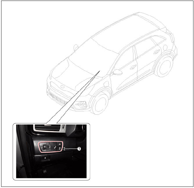
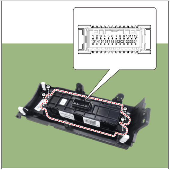
- ESP OFF swtich
Description
- The ESP OFF switch is for the user to turn off the ESP system.
- The ESP OFF lamp is on when ESP OFF switch is engaged.
Removal
- Turn ignition switch OFF and disconnect the negative (-) battery terminal.
- Remove the crash pad lower panel.
(Refer to Body (Interior and Exterior) - "Crash Pad Lower Panel")
- Loosen the mounting screw, remove the crash pad garnish assembly (LH) (A).
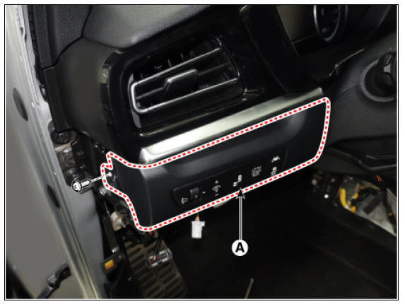
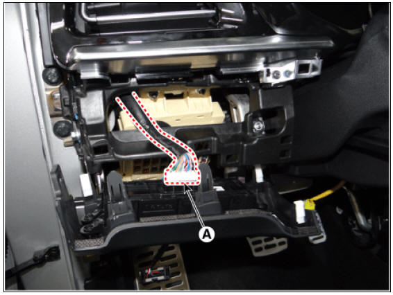
- Disconnect the crash pad side switch connector (A).
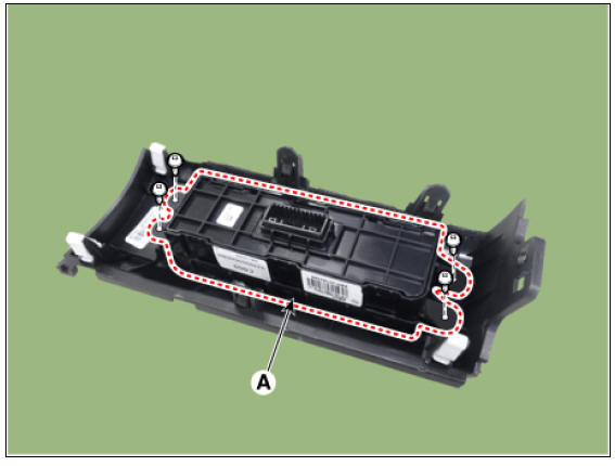
- Remove the crash pad side switch (A) after loosening the mounting screws
- Install in the reverse order of removal.
Inspection
- Check for continuity between the terminals. If there is an abnormality, replace the switch.
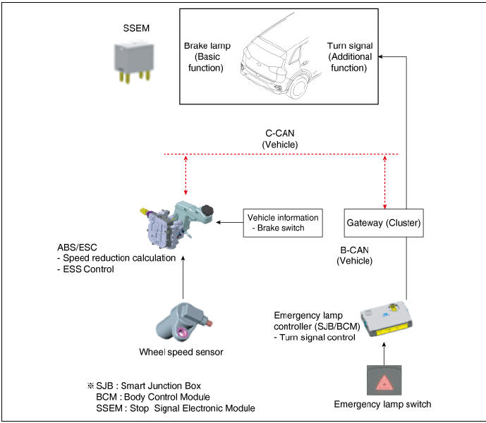
Emergency Signal System Description and operation
Description
Introduction of quick brake warning system (ESS)
In case of quick brake by driver, the brake lamp or turn signal is blinked to warn against the vehicle at rear.
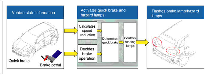
- Basic function (Blinking the brake lamp/emergency lamp)
- Operation condition: In case of quick brake or operation of ABS above in a certain speed
- Releasing condition: In case of stopping the quick brake or releasing the ABS operation
- Additional function (Blinking the turn signal)
- Operation condition: In case of quick brake in low speed
- Releasing condition: Releasing at the start of driving
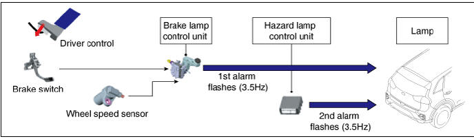
System configuration
ESS Circuit diagram
READ NEXT:
 Body (Interior And Exterior) - Troubleshooting
Troubleshooting
Symptom:
Water leaks from
panorama sunroof
Suspected Area → Remedy
Deteriorated roof lid
weatherstrip → Replace
Excessive roof lid-tobody
clearance and
improperly fitted
weatherstrip → A
SEE MORE:
Memory Power Seat Switch
Connector and Terminal Function
Memory power seat switch Repair procedures
Removal
Disconnect the negative (-) battery terminal.
Remove the driver front door trim.
(Refer to Body - "Front Door Trim")
Remove the memory power
Adjusting the front seat
Operation
The seat can be adjusted by using the
control levers located on the outside of
the seat cushion.
INFORMATION
Adjust the seat before driving, and make
sure the seat is locked securely by trying
to move without using the lever. If the
Categories
- Home
- KIA Niro EV, Hybrid - Second generation - (SG2) (2021-2024) - Owner's manual
- Kia Niro - First generation - (DE) (2017-2022) - Service and Repair Manual
- Contact Us