KIA Niro: Front Hub / Knuckle
Components
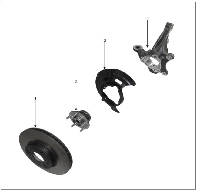
- Brake disc
- Hub assembly
- Dust cover
- Knuckle
Front Hub / Knuckle / Repair Procedures
Removal
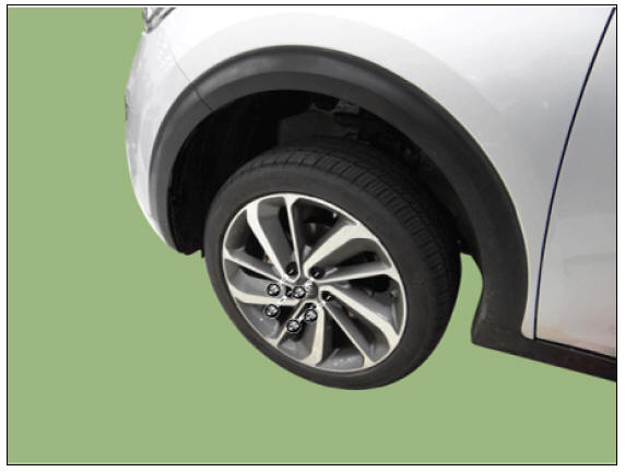
- Remove the wheel and tire.
Tightening torque : 107.9 - 127.5 N*m (11.0 - 13.0 kgf*m, 79.6 - 94.0 lb*ft)
Warning
Be careful not to damage the wheel nuts when removing the wheel and tire.
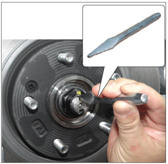
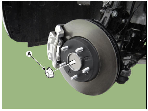
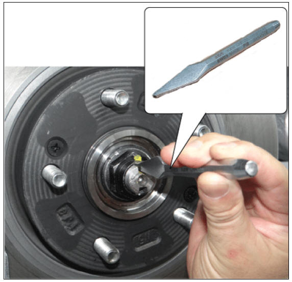
- By hammering on a chisel, unlock the driveshaft lock hub nut caulking.
Warning
If there is screw thread (A) on the end of the nut, unlock the caulking by using a chisel and then loosen the nut to prevent damaging driveshaft screw thread.
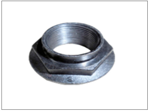
- Remove the caulking nut (A) from the front axle.
Tightening torque : 274.6 - 294.2 N*m (28.0 - 30.0 kgf*m, 202.5 - 217.0 lb*ft)
Warning
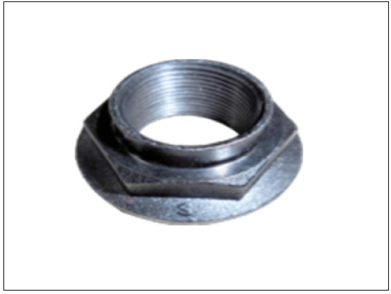
The driveshaft lock nut must be replaced with new one. When
replacing the drive lock hub nut, use only the
nut with screw thread (A) on the end

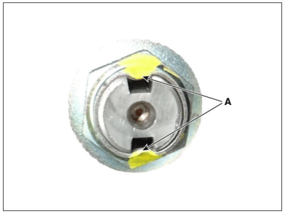
- Tighten the driveshaft lock hub nut to the specified tightening torque, and caulk by using a chisel and hammer.
- If there are two key seats, perform on all two seats.
Caulking depth (A) : 1.5 mm (0.0591 in)
- Remove the front caliper.
(Refer to Brake System - "Front disck brake")
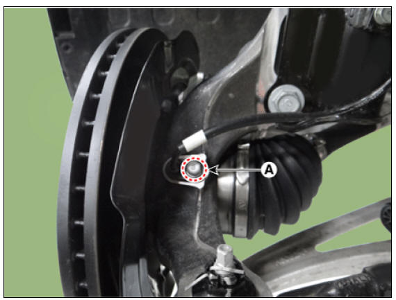
- Remove the wheel speed sensor bolt (A).
Tightening torque : 6.8 - 10.7 N*m (0.7 - 1.1 kgf*m, 5.0 - 7.9 lb*ft)
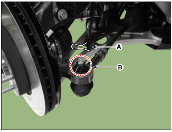
- Remove the tie rod end pin (A) and nub (B).
Tightening torque : 78.4 - 98.0 N*m (8.0 - 10.0 kgf*m, 57.8 - 72.3 lb*ft)
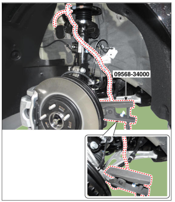
- Remove the knuckle by using the SST (09568-34000).
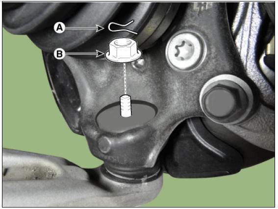
- Loosen the pin (A), and then remove the lower arm nut (B).
Tightening torque : 98.0 - 117.6 N*m (10.0 - 12.0 kgf*m, 72.3 - 86.7 lb*ft)
- Loosen the strut bolt and then remove the front axle.
Tightening torque : 156.9 - 176.5 N*m (16.0 - 18.0 kgf*m, 115.7 - 130.2 Ib*ft)
Disassembly
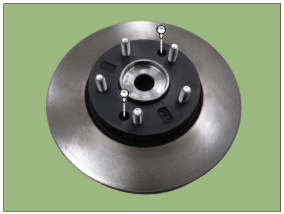
- Loosen the screw, and then remove the brake disc.
Tightening torque : 4.9 - 5.8 N*m (0.5 - 0.6 kgf*m, 3.6 - 4.3 Ib*ft)
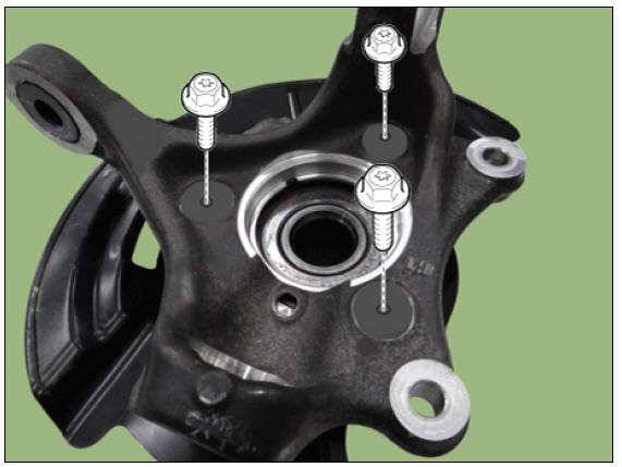
- Remove the hub assembly mounting bolts from the knuckle.
Tightening torque : 88.2 - 107.8 N*m (9.0 - 11.0 kgf*m, 65.0 - 79.5 lb*ft)
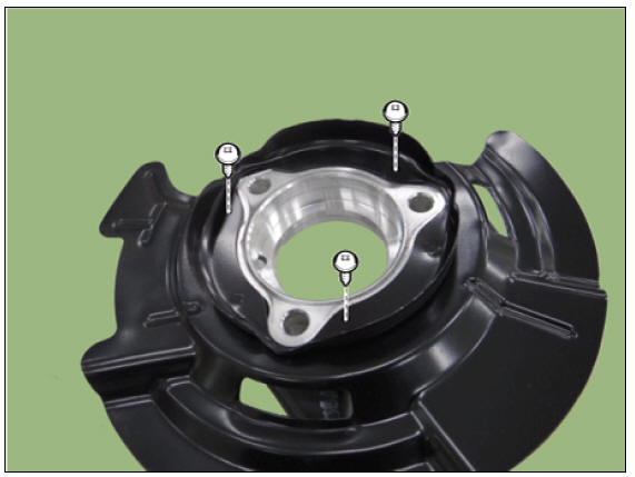
- Loosen the dust cover bolts and then remove the dust cover.
Tightening torque : 6.8 - 10.7 N*m (0.7 - 1.1 kgf*m, 5.0 - 7.9 lb*ft)
Inspection
- Check the hub for cracks and the splines for wear.
- Check the brake disc for scoring and damage.
- Check the knuckle for cracks
- Check the bearing for cracks or damage.
Removal and
Installation
- Remove the front wheel and tire.
(Refer to Suspension System - "Wheel")
- Disconnect the front wheel speed sensor (A).
Tightening torque : 7.8 - 11.8 N*m (0.8 - 1.2 kgf*m, 5.8 - 8.7 lb*ft)
- Disconnect the brake hose bracket (A) by loosening the bolt.
Tightening torque : 8.8 - 13.7 N*m (0.9 - 1.4 kgf*m, 6.5 - 10.1 lb*ft)
- By hammering on a chisel, unlock the driveshaft lock hub nut caulking.
Warning
If there is screw thread (A) on the end of the nut, unlock the
caulking by using a chisel and then loosen the nut
to prevent damaging driveshaft screw thread.
- Remove the caulking nut (A) from the front axle.
Tightening torque: 274.6 - 294.2 N*m (28.0 - 30.0 kgf*m, 202.5 - 217.0 lb*ft)
Warning
The driveshaft lock nut must be replaced with new one. When
replacing the drive lock hub nut, use only the
nut with screw thread (A) on the end.

- Tighten the driveshaft lock hub nut to the specified tightening torque, and caulk by using a chisel and hammer.
- If there are two key seats, perform on all two seats.
Caulking depth (A) : 1.5 mm (0.0591 in)

- Remove the front brake disc.
(Refer to Brake System - "Front Disc Brake")
- Using a SST (09517-4E000), disconnect the driveshaft from the axle hub.
Warning
Do not pull or twist excessively to remove the axle when the drive shaft is disassembled.
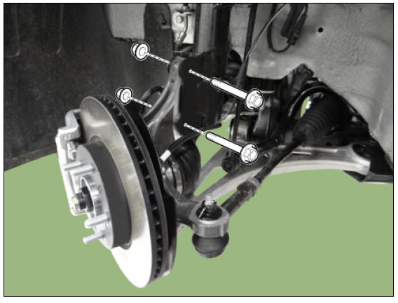
- Loosen the bolts and remove the hub bearing assembly (A) from the front knuckle.
Tightening torque: 88.3 - 107.9 N*m (9.0 - 11.0 kgf*m, 65.1 - 79.6 lb*ft)
- Install in the reverse order of removal.
READ NEXT:
 Rear Axle Assembly / Rear Hub - Carrier
Components
Disc
Dust cover
Rear hub
Rear Knuckle
Rear Hub - Carrier / Repair Procedures
Removal
Remove the tire (A).
Tightening torque :
107.9 - 127.5 N*m (11.0 - 13.0 kgf*m, 79.6 - 94.0 lb*ft)
Warning
Be careful not t
Suspension System
Service
Data
Front Suspension
Rear Suspension
Wheel & Tire
Wheel Alignment
Tightening
Torques
Front Suspension
Rear Suspension
Special Service Tools
Tool Name / Number / IIIustration
/ Description
Troubleshooting - Suspension System
Symptom:
Heavy weight feeling on steering wheel
Expected cause - Countermeasure
Faulty on front wheel alignment - Adjust or
repair
Over rotation resistance of lower arm
ball joint - Replace
Over rotation resistance of strut
b
SEE MORE:
Tailgate
Opening/closing the manual tailgate
Operation
Press the outside handle switch (1) to
open the tailgate.
Pull up the tailgate.
Push down the tailgate to close it.
Make sure that the tailgate is securely
latched.
Operating conditi
Distance to
empty
The distance to empty is displayed differently
according to the selected drive
mode in the Drive Mode Integrated Control
System.
For more information, refer to "Drive
mode integrated control system"
When destination is not set
Categories
- Home
- KIA Niro EV, Hybrid - Second generation - (SG2) (2021-2024) - Owner's manual
- Kia Niro - First generation - (DE) (2017-2022) - Service and Repair Manual
- Contact Us