KIA Niro: Front / Rear Outlet Cooling Duct
Kia Niro - First generation - (DE) (2017-2022) - Service and Repair Manual / Hybrid Control System / High Voltage Battery Cooling System / Front / Rear Outlet Cooling Duct
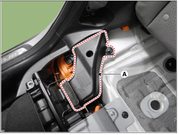
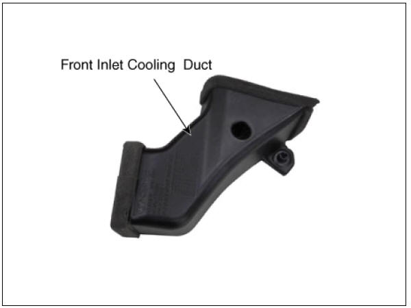
Front Outlet Cooling Duct
- Switch "OFF" the ignition and disconnect the negative (-) terminal of the auxiliary 12V battery.
- Shut off the high voltage circuit.
(Refer to Hybrid Control System - "High Voltage Shutoff Procedure")
- Remove the rear seat cushion.
(Refer to Body - "Rear Seat Assembly")
- Remove the front outlet duct (A).
Rear Outlet Cooling Duct
- Switch "OFF" the ignition and disconnect the negative (-) terminal of the auxiliary 12V battery.
- Shut off the high voltage circuit.
(Refer to Hybrid Control System - "High Voltage Shutoff Procedure")
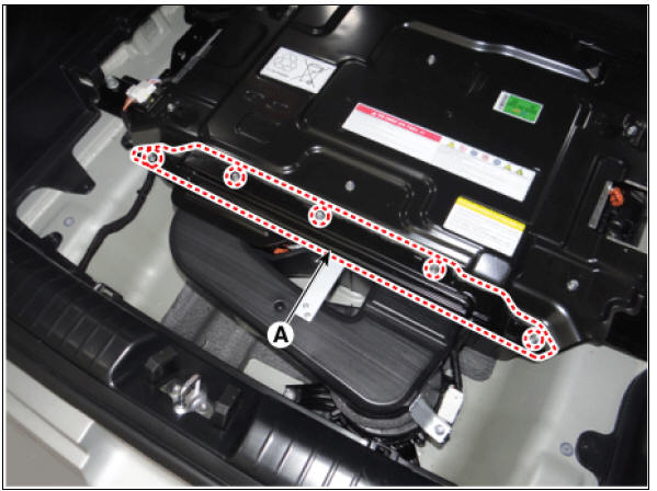
- Remove the high voltage rear cover (A) after loosening the mounting bolt.
High Voltage Battery Rear Cover mounting bolt : 7.8 - 11.8 N*m (0.8 - 1.2 kgf*m, 5.8 - 8.7 lb*ft)
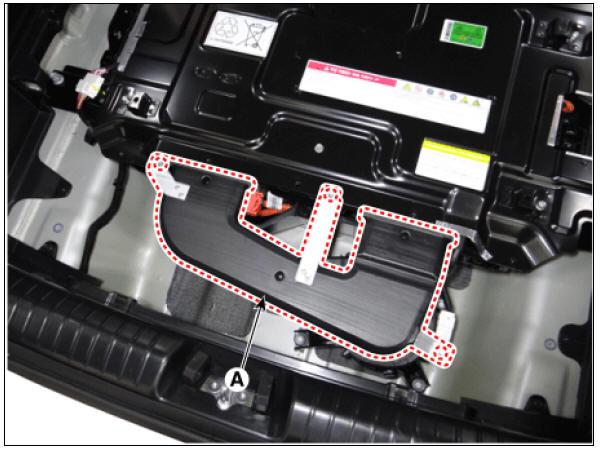
- Remove the rear outlet cooling duct (A) after loosening the mounting bolt.
Rear Outlet Cooling Duct mounting bolt : 7.8 - 11.8 N*m (0.8 - 1.2 kgf*m, 5.8 - 8.7 lb*ft)
Installation
Warning
- Be sure to read and follow the "General Safety Information and Caution" before doing any work related with the high voltage system. Failure to follow the safety instructions may result in serious electrical injuries.
- Be sure to read and follow the "High Voltage Shut-off Procedures" before doing any work related with the high voltage system. Failure to follow the safety instructions may result in serious electrical injuries.
- Install the cooling ducts in the reverse order of removal.
Air Inlet Temperature Sensor
Battery Temperature Sensor (Side of cell)

READ NEXT:
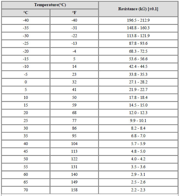
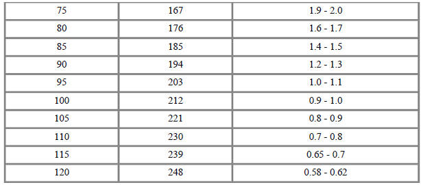
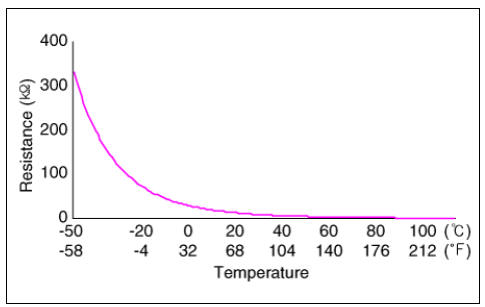
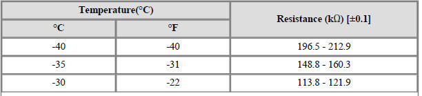
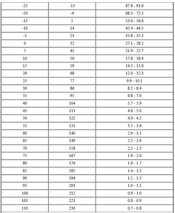
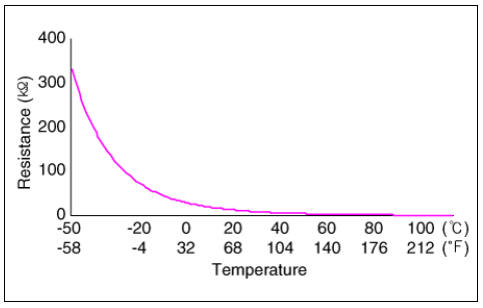
 Inlet Temperature Sensor
Inlet Temperature Sensor #1 (Main High Voltage)
Description
The inlet temperature sensor is installed on top of the high voltage battery
module, and it detects the
air temperature inside the battery system assembly.
The inlet temperatur
Low Voltage DC/DC Converter
Specification
Description
The Low Voltage DC/DC is integrated into the HPCU. It charges the auxiliary
battery as a substitute
for generator by converting the high voltage (DC 270V) from the high voltage
battery into low voltage
(DC 12V).
Power Cable
Components
Power Cable (HPCU↔Main High Voltage Battery
System)
Power Cable (HPCU↔HSG, Electric /C Compressor)
Power Cable (Main High Voltage Battery System ↔ Sub
High Voltage Battery System)
Removal
Warning
SEE MORE:
Exterior overview
Front view
* The actual features in your vehicle may not necessarily be available due to
the
selected options or regions.
Hood
Head lamp
Wheel and tire
Outside rear view mirror
Sunroof
Front windshield wiper blades
Windows
F
Rear Cross Member Repair procedures
Removal
Disconnect the battery negative cable.
Remove the wheel and tire.
Tightening torque:
107.9 - 127.5 N*m (11.0 - 13.0 kgf*m, 79.6 - 94.0 lb*ft)
Warning
Be careful not to damage the wheel nuts when removing the wheel and
tire.
Categories
- Home
- KIA Niro EV, Hybrid - Second generation - (SG2) (2021-2024) - Owner's manual
- Kia Niro - First generation - (DE) (2017-2022) - Service and Repair Manual
- Contact Us