KIA Niro: Inhibitor Switch Repair procedures
Inspection
Warning
Inspect the following items by referring to inspection flow chart.
(Refer to Inhibitor Switch - "Troubleshooting")
- Check the diagnostic trouble codes (DTC) using KDS.
- Inspect if "N" range setting matches.
(Refer to Inhibitor Switch - "Installation")
- Check the free play for shift cable.
(Refer to Shift Cable - "Installation")
- Check the condition of connector.
(1) Inspect connector thoroughly for looseness, poor connection, bending, corrosion, contamination, deformation, or damage.
(2) Turn Ignition "ON" and engine "OFF" and measure the power supplied to inhibitor switch circuit and voltage between ground.
Specification : Approx. 12 V
- Inspect ground condition of rear combination lamp circuit.
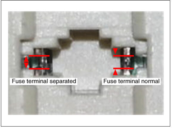
- Inspect wiring connection condition of junction box power terminal and fuse lamp.
(1) Check if the fuse holder is separated and that the holder is tightly holding the fuse.
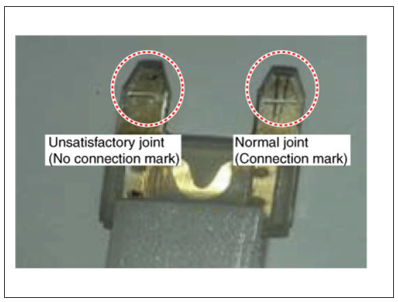
(2) Attach tester fuse to check if it is connected properly.
(3) Check if fuse is damaged.
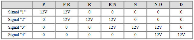
- Check the inhibitor switch circuit signal.
(1) Turn Ignition "ON", & engine "OFF".
(2) Measure the voltages between each signal terminal and chassis ground in each range (P, R, N, D).
Specification : Approx. 12 V
Signal Code Table
Removal
Warning
- Be sure to read and follow the "General Safety Information and Caution" before doing any work related with the high voltage system. Failure to follow the safety instructions may result in serious electrical injuries.
- Be sure to shut off the high voltage circuit according to the "High Voltage Shut-off Procedures" before doing any work related with the high voltage system to avoid serious electrical injuries.
- Place the shift lever in the "N" position.
- Shut off the high voltage circuit.
(Refer to Double Clutch Transmission System - "High Voltage Shut-off Procedure")
- Drain the coolant of hybrid cooling system.
(Refer to Hybrid Motor System - "Coolant")
- Remove the hybrid power control unit (HPCU) assembly.
(Refer to Hybrid Control System - "Hybrid Power Control Unit")
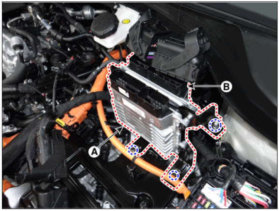
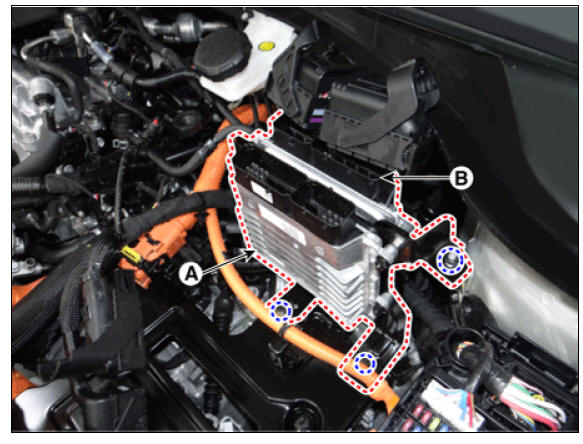
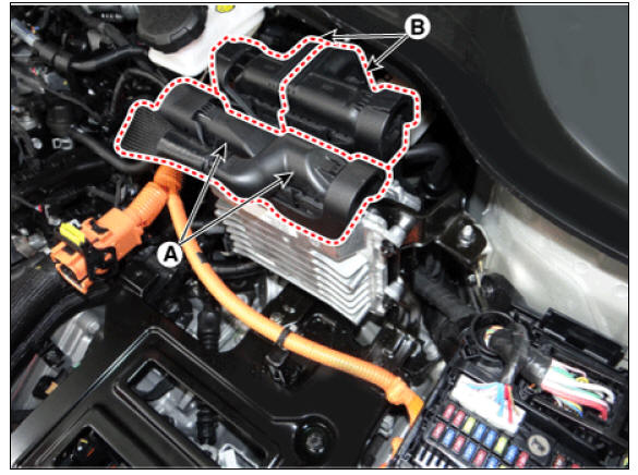
- Disconnect the TCM connector (A) and ECM connector (B).
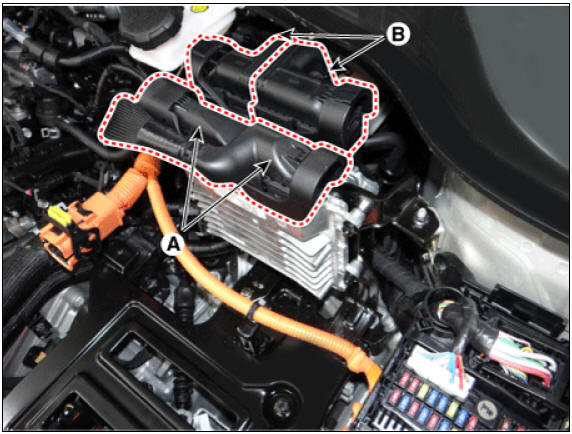
- Remove the TCM (A) and ECM (B).
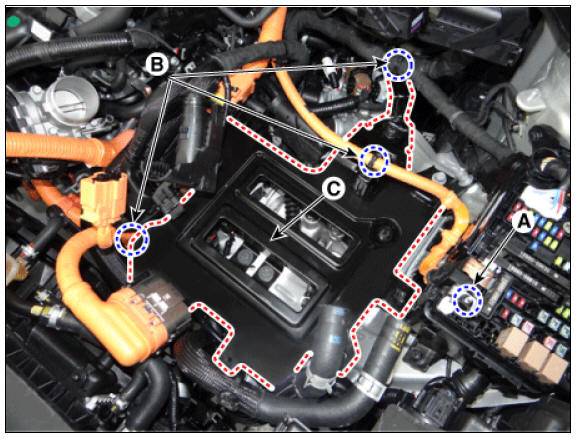
- Remove the HPCU tray (C) after removing the nut (A) and wiring mounting clips (B).
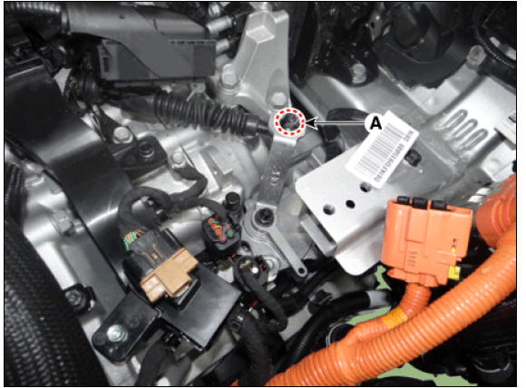
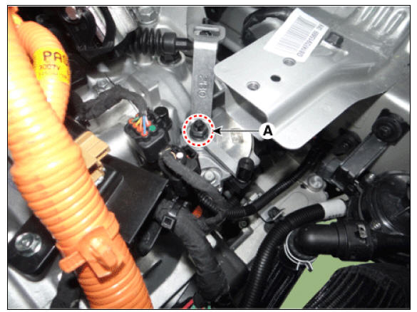
- Loosen the shift cable mounting nut (A).
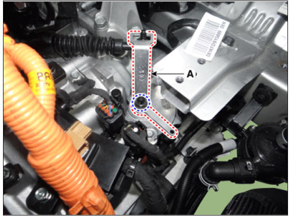
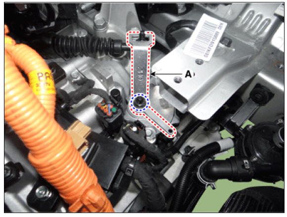
- Remove the manual control lever (A).
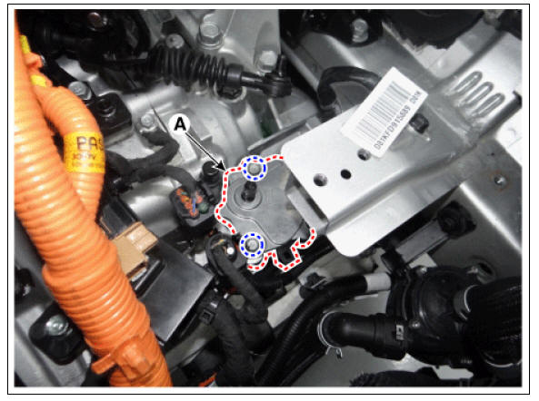
- Remove the inhibitor switch (A).
Installation
- Check that the shift lever is placed in the "N" position.
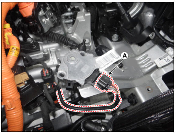
- Conntect the inhibitor switch connector (A).
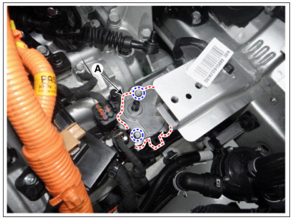
- Install the inhibitor switch (A).
Warning
Lightly tighten the inhibitor switch mounting bolts so that necessary adjustments can be made.
- Install the manual control lever (A).
Warning
Lightly tighten the manual control lever nut so that necessary adjustments can be made.
- Align the hole in the manual control lever with the "N" position hole of the inhibitor switch and then insert the SST inhibitor switch guide pin (0K948-E4000).
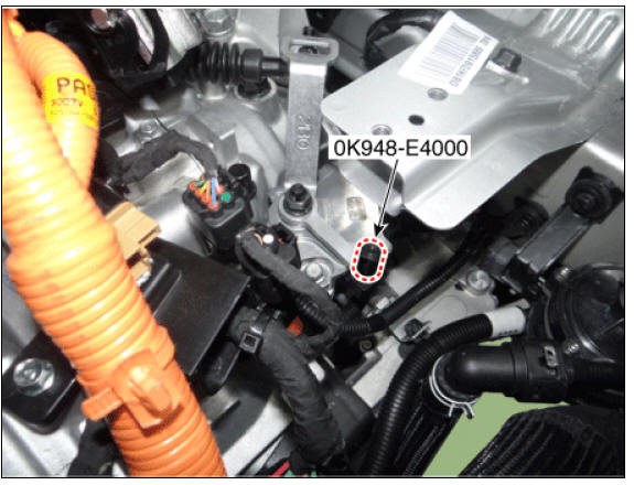
- Tighten the manual lever mounting nut (A) to the specified torque.
Tightening torque : 17.7 - 24.5 N*m (1.8 - 2.5 kgf*m, 13.0 - 18.1 lb*ft)
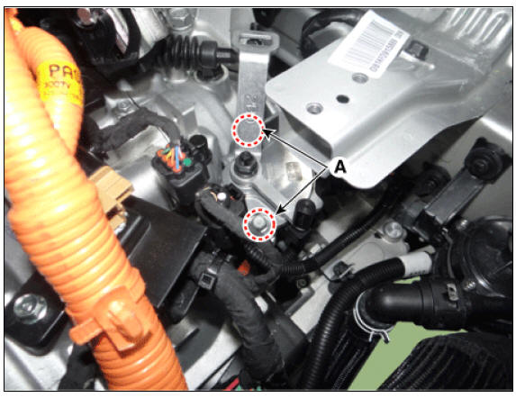
- Tighten the inhibitor switch mounting bolts (B) to the specified torque.
Tightening torque: 9.8 - 11.8 N*m (1.0 - 1.2 kgf*m, 7.2 - 8.7 lb*ft)
- Tighten the nut (A) to the specified torque after removing free play by pushing the shift cable in the direction of the arrow.

- Remove the SST (0K948-E4000) from the adjusment hole.
- Install the HPCU tray (A).
Tightening torque: (A) 21.6 - 23.5 N*m (2.2 - 2.4 kgf*m, 15.9 - 17.4 lb*ft)
- Install the wiring mounting clips (B) to HPCU tray and the tighten the nut (C).
Tightening torque: (C) 10.8 - 13.7 N*m (1.1 - 1.4 kgf*m, 8.0 - 10.1 lb*ft)
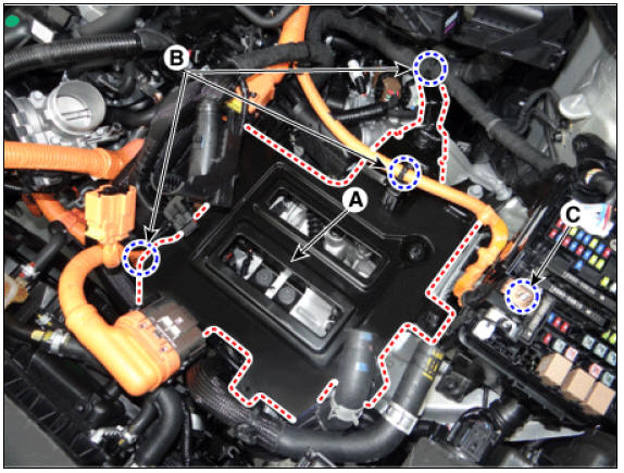
- Install the TCM (A) and ECM (B).
Tightening torque : 9.8 - 11.8 N*m (1.0 - 1.2 kgf*m, 7.2 - 8.7 lb*ft)
- Connect the TCM connector (A) and ECM (B) connector.
- Install the hybrid power control unit (HPCU) assembly.
(Refer to Hybrid Control System - "Hybrid Power Control Unit")
- Refill the hybrid motor cooling system with coolant.
(Refer to Hybrid Motor System - "Coolant")
- Connect the high voltage circuit.
(Refer to Double Clutch Transmission System - "High Voltage Shut-off Procedure")
READ NEXT:
 Shift Lever | Shift Cable
Components
Shift lever knob & boots
Shift lever assembly
Shift cable assembly
Shift Lever Repair procedures
Removal
Shift the gear to "N".
Remove the knob (A) by pulling it in the direction of arrow af
SEE MORE:
Fuel Filler Door Release Actuator Repair procedures | Fuel Filler Door Open Switch
Fuel Filler Door / Components And Components Location
Fuel filler door open switch
Fuel filler door release actuator
Fuel Filler Door Release Actuator Repair procedures
Removal
Disconnect the negative (-) battery termin
Door locks inside the vehicle
Unlocking with the door handle
Operation
Front door
If the inner door handle is pulled once
when the door is locked, the door will
unlock and open.
Rear door
If the inner door handle is pulled once
when the door is locked, the d
Categories
- Home
- KIA Niro EV, Hybrid - Second generation - (SG2) (2021-2024) - Owner's manual
- Kia Niro - First generation - (DE) (2017-2022) - Service and Repair Manual
- Contact Us