KIA Niro: Shift Lever | Shift Cable
Components
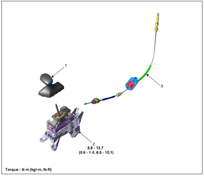
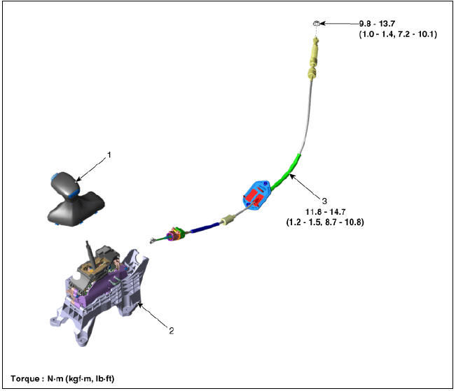
- Shift lever knob & boots
- Shift lever assembly
- Shift cable assembly
Shift Lever Repair procedures
Removal
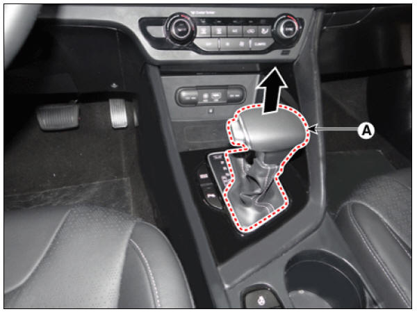
- Shift the gear to "N".
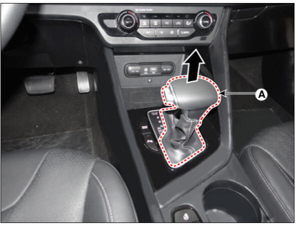
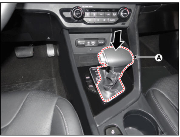
- Remove the knob (A) by pulling it in the direction of arrow after removing the boots from the console upper cover.
- Remove the floor console assembly.
(Refer to Body - "Floor Console Assembly")
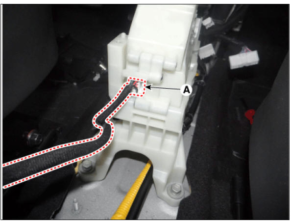
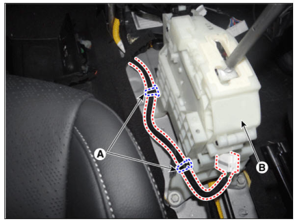
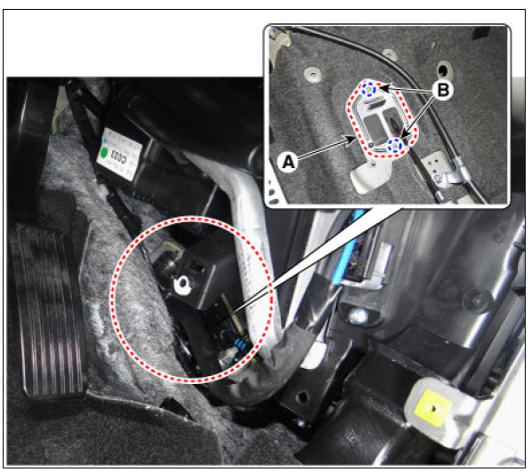
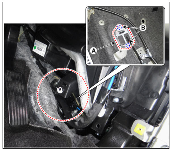
- Disconnect the main connector (A).
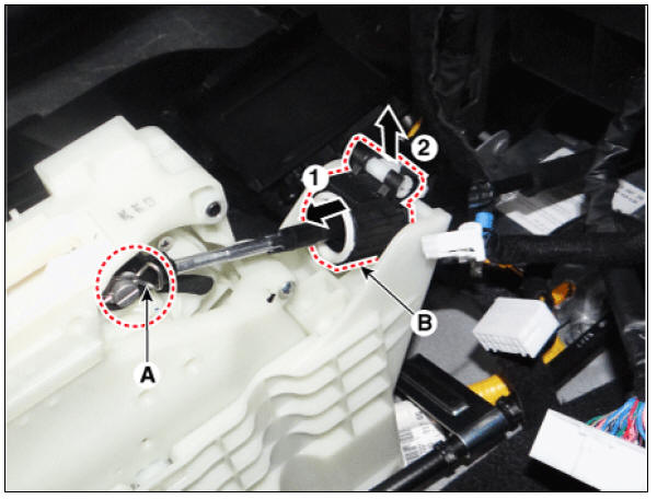
- Remove the shift cable.
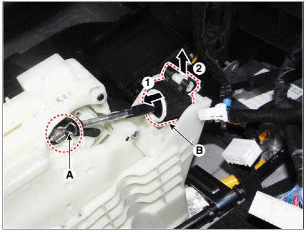
(1) Remove the shift cable from the shift lever pim after removing the snap pin (A).
(2) Remove the cable socket (B) from the shift lever.
- Remove the shift lever assembly (B) by loosening bolts and then remove the wiring mounting clips (A).
Tightening torque: 8.8 - 13.7 N*m (0.9 - 1.4 kgf*m, 6.5 - 10.1 lb*ft)
Installation
- Install in the reverse order of removal.
Warning
Check that the shift lever and manual control lever are placed in the "N" position.
Shift Cable
Components
- Shift lever knob & boots
- Shift lever assembly
- Shift cable assembly
Shift Cable Repair procedures
Removal
Warning
- Be sure to read and follow the "General Safety Information and Caution" before doing any work related with the high voltage system. Failure to follow the safety instructions may result in serious electrical injuries.
- Be sure to shut off the high voltage circuit according to the "High Voltage Shut-off Procedures" before doing any work related with the high voltage system to avoid serious electrical injuries.
- Place the shift lever in the "N" position.
- Shut off the high voltage circuit.
(Refer to Double Clutch Transmission System - "High Voltage Shut-off Procedure")
- Drain the coolant of hybrid cooling system.
(Refer to Hybrid Motor System - "Coolant")
- Remove the hybrid power control unit (HPCU) assembly.
(Refer to Hybrid Control System - "Hybrid Power Control Unit")
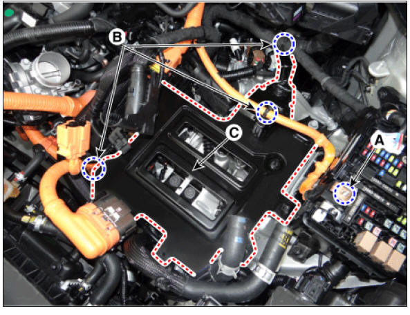
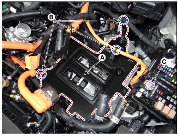
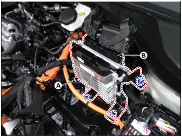
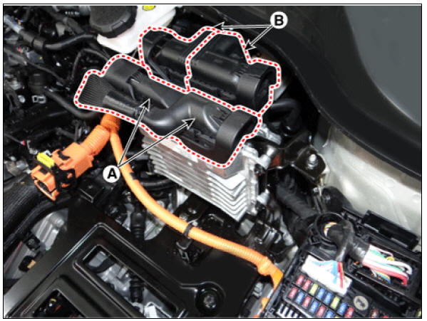
- Disconnect the TCM connector (A) and ECM connector (B).
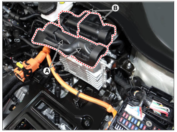
- Remove the TCM (A) and ECM (B).
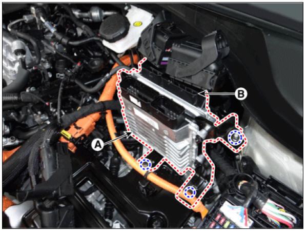
- Remove the HPCU tray (C) after removing the nut (A) and wiring mounting clips (B).
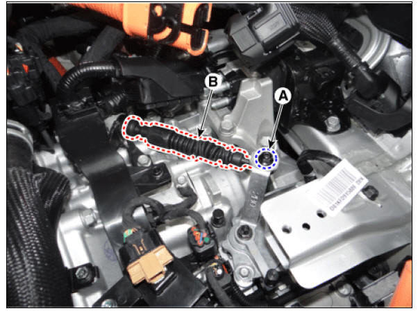
- Loosen the nut (A) and then remove the shift cable (B) from the bracket.
- Remove the knob (A) by pulling it in the direction of arrow after removing the boots from the console upper cover.
- Remove the floor console assembly.
(Refer to Body - "Floor Console Assembly")
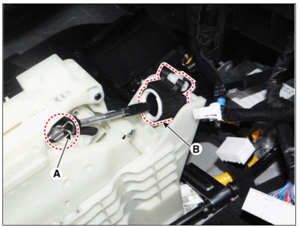
- Remove the shift cable.
(1) Remove the shift cable from the shift lever pim after removing the snap pin (A).
(2) Remove the cable socket (B) from the shift lever.
- Remove the shift cable retainer (A) after loosening the nuts (B). Then, remove the shift cable by pulling it toward the vehicle interior.
Installation
- Check that the shift lever is placed in the "N" position.
- Install the shift cable retainer (A) by tightening nuts (B).
Tightening torque : 11.8 - 14.7 N*m (1.2 - 1.5 kgf*m, 8.7 - 10.8 lb*ft)
- Install the shift cable.
(1) Install the cable socket (A).
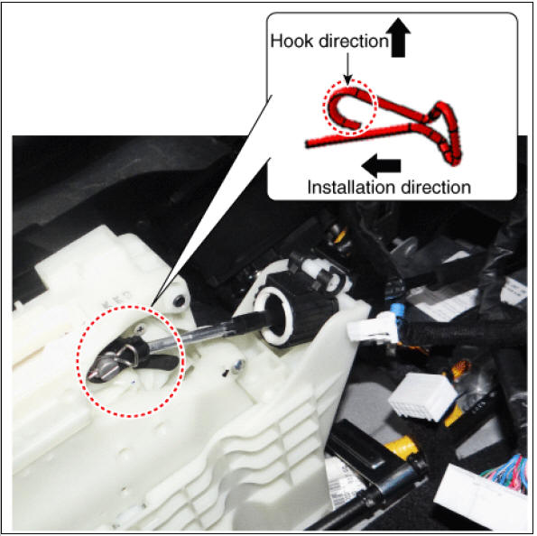
(2) Install the shift cable to the lever pin and then insert the snap pin (A).
Warning
- Install the shift cable after checking the direction of projection to prevent incorrect assembly.
- Mind the installation direction of snap pin and install the snap pin with the hook facing upward.
- Install the floor console assembly.
(Refer to Body - "Floor Console Assembly")
- Install the knob (A) by pressing it in the direction of arrow after installing the boots to the console upper cover.
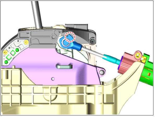
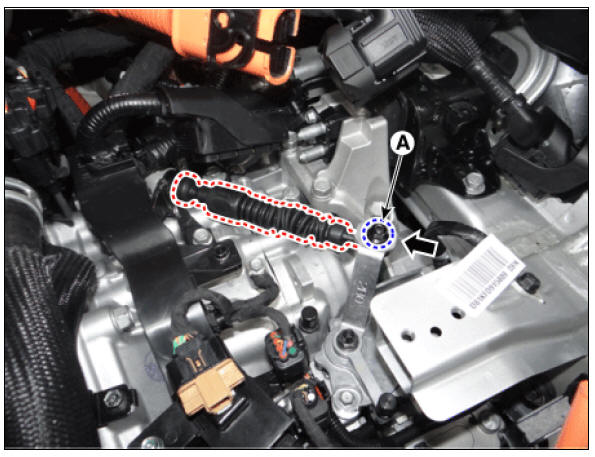
- Tighten the nut (A) to the specified torque after removing free play by pushing the shift cable in the direction of the arrow.
Tightening torque : 8.8 - 13.7 N*m (0.9 - 1.4 kgf*m, 6.5 - 10.1 lb*ft)
Warning
The existing shift cable clip (A) must be replaced with new one. (Do not reuse it.) 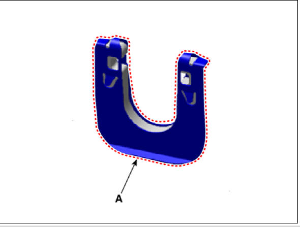
- Install the HPCU tray (A).
Tightening torque : (A) 21.6 - 23.5 N*m (2.2 - 2.4 kgf*m, 15.9 - 17.4 lb*ft)
- Install the wiring mounting clips (B) to HPCU tray and the tighten the nut (C).
Tightening torque : (C) 10.8 - 13.7 N*m (1.1 - 1.4 kgf*m, 8.0 - 10.1 lb*ft)
- Install the TCM (A) and ECM (B).
Tightening torque : 9.8 - 11.8 N*m (1.0 - 1.2 kgf*m, 7.2 - 8.7 lb*ft)
- Connect the TCM connector (A) and ECM (B) connector.
- Install the hybrid power control unit (HPCU) assembly.
(Refer to Hybrid Control System - "Hybrid Power Control Unit")
- Refill the hybrid motor cooling system with coolant.
(Refer to Hybrid Motor System - "Coolant")
- Connect the high voltage circuit.
(Refer to Double Clutch Transmission System - "High Voltage Shut-off Procedure")
READ NEXT:
 Dual Clutch Assembly
Components
Retaining ring
Spline hub
Snap ring
Dual clutch assembly
Dual Clutch Assembly Repair procedures
Removal
Remove the hybrid drive motor & dual clutch transmission assembly from
the vehicle.
(Refer to DCT Syst
SEE MORE:
Power/Charge
gauge
The Power/Charge Gauge shows the
energy consumption rate of the vehicle
and the charge/discharge status of the
regenerative brakes.
Power: It shows the energy consumption
rate of the vehicle when driving
uphill or accelerating. The mor
Safety precautions for electric vehicle
If an accident occurs
If towing is required, tow the vehicle with
a flatbed equipment or dollies with all
wheels off the ground.
Dollies
If you must tow the vehicle using only
two wheels, lift the rear wheels off the
ground an
Categories
- Home
- KIA Niro EV, Hybrid - Second generation - (SG2) (2021-2024) - Owner's manual
- Kia Niro - First generation - (DE) (2017-2022) - Service and Repair Manual
- Contact Us